Scroll to:
Mathematical model of blast furnace hearth condition based on data from thermocouples in refrigerator belts
https://doi.org/10.17073/0368-0797-2025-3-316-323
Abstract
The control of blast furnace hearth lining is of critical importance in ensuring efficient and safe operation of blast furnace production process. Hearth lining plays a fundamental role in protecting the blast furnace walls from high temperatures and chemically aggressive slag melt. Early detection of high wear areas allows planning of preventive maintenance, thereby minimizing downtime and lost productivity. Furthermore, it contributes to the efficient use of resources by optimizing the replacement of damaged lining sections, thus avoiding unnecessary expenditure on preventive measures. The paper presents a three-dimensional unsteady model of blast furnace hearth, developed based on thermocouple data. This model facilitates estimation of the crucible heat-up and temperature distribution in the crucible masonry in three-dimensional and two-dimensional (graphical) forms. Estimation of the hearth lining burnout is achieved through the utilization of readings of the thermocouples installed in the hearth lining of blast furnace in the area encompassing the three lower refrigerator belts. Implementation of the mathematical model is permissible at any juncture following the overhaul of the first discharge. If a sufficient amount of time passed since the blast furnace was blown in, and there is a possibility of burnout or skull formation in the hearth lining, it is also necessary to utilize the results of ultrasonic control (USC) of the blast furnace lower part. The mathematical model of the blast furnace hearth condition enables informed decision-making by users regarding prevention of the emergency situations related to lining burnout, thus demonstrating its potential as a tool for enhancing the efficiency and safe operation of blast furnaces.
Keywords
For citations:
Dmitriev A.N., Vit’kin D.A., Zolotykh M.O., Vit’kina G.Yu. Mathematical model of blast furnace hearth condition based on data from thermocouples in refrigerator belts. Izvestiya. Ferrous Metallurgy. 2025;68(3):316-323. https://doi.org/10.17073/0368-0797-2025-3-316-323
Introduction
Effective control of hearth lining burnout in a blast furnace (BF) is an integral part of the comprehensive blast furnace process control system aimed at achieving high technical and economic performance.
There are several methods for monitoring hearth lining burnout in blast furnaces:
– application of systems analysis principles and solving direct and inverse problems of blast furnace heat performance control [1 – 3];
– systematic diagnostics of hearth lining condition using the reflected acoustic-ultrasonic signal (AU-E) method developed by the company [4];
– the method of group argument accounting, where the silicon content in hot metal is taken as the primary parameter for assessing the thermal state of the BF hearth [5];
– determination of the average heat flux of cooling water in the refrigerators [6; 7];
– analysis of the relationship between hearth lining design and lining wear [8 – 10].
One of the most reliable methods involves the installation of special thermocouples at specific points and in a defined number during a major overhaul. This subsequently allows for the monitoring of the thickness of the lining layers and assessment of the temperature gradient within the masonry [11 – 14]. The remaining thickness of the hearth and bottom lining, along with their two- and three-dimensional visualization, is calculated using both commercial software packages (e.g., Matlab [15]) and proprietary software solutions [16 – 18]. Among the available approaches, the finite element method is considered the most illustrative for modeling heat transfer [19; 20].
Monitoring the condition of the refractory hearth lining using a mathematical model [21] is feasible after the furnace blow-in and stabilization of its thermal regime. The mathematical model presented in this paper can be applied at any time after the overhaul of the first discharge category. If a significant amount of time has passed since the furnace was blown in, burnout or skull formation may occur in the hearth lining. In this case, it becomes necessary to use the results of ultrasonic control (USC) of the lower part of the blast furnace.
Input data
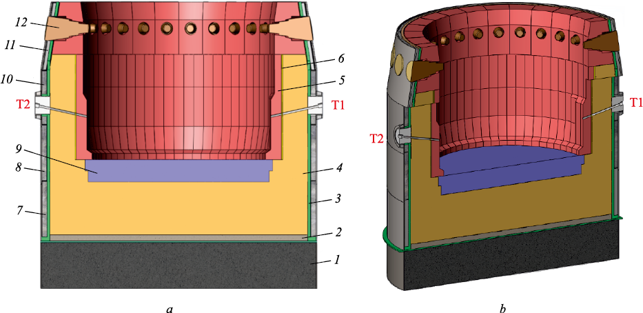
Fig. 1 shows a vertical section of the hearth of a 2000 m3 blast furnace. It can be seen that the first refrigerator belt covers most of the bottom, while the second and third belts are located in the hearth crucible zone.
Fig. 1. Vertical section of the blast furnace hearth, including the bottom: |
Thermocouples are installed in front of the three refrigerator belts in the hearth and bottom zones (20 thermocouples per belt). The data from these thermocouples, stored in the blast furnace automated process control system (APCS) database, can be used to assess hearth burnout. The data sampling interval may be as short as one minute. The concept of reference thermocouple temperatures (RTT) is introduced – these are the thermocouple readings taken at the moment of ultrasonic control (USC) for hearth burnout. The USC results provide information on the thickness of all refractory lining layers at four vertical levels. According to the results of the USC, wear of the ceramic blocks and carbon blocks, as well as the presence of skull formation, is observed in the hearth belt. The horizontal sections were taken at elevations of 6.5, 7.3, 7.9, and 9.9 m.
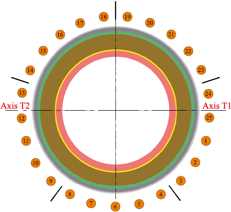
Fig. 2 presents a horizontal section of the hearth referenced to the tuyeres and tapholes. The origin of the cylindrical coordinate system is located at the center of the bottom at elevation 0. The zero-angle reference is aligned with the axis of tuyere 1 (Fig. 2), followed clockwise with equal angular intervals. In this system, the height remains constant and corresponds to the elevation of the slicing plane.
Fig. 2. Horizontal section of the furnace hearth |
Thus, four slicing planes define the geometry of the skull formation. Using CAD software, a highly accurate 3D model of the hearth skull can be generated.
The computational domain includes the sidewall zone of the hearth and the bottom zone, where heat transfer is described by the heat conduction equation for solid materials. The initial conditions are the known data from the latest USC (reference temperatures). The internal boundary is the contact surface between the molten metal and the lining (skull). The temperature of the inner surface of the lining is assumed to be equal to the current temperature of the hot metal, measured by thermocouples installed in the blast furnace taphole. If such thermocouples are absent, the temperature is assigned by the operator (e.g., 1450 °C). The external boundary condition is defined by the thermocouple readings in the refrigerator belts. It is assumed that the temperature of the cooling agent in the refrigerators remains constant. For simplification, an ideal thermal contact between lining layers is assumed. In the interface zones, the thermophysical properties of the materials are averaged.
Heat transfer through a multilayer cylindrical wall
The linear heat flux density through a cylindrical wall was calculated using formulas (1) – (3)
| \[\begin{array}{c}q = \frac{{\pi ({T_1} - {T_2})}}{{\frac{1}{{{\alpha _1}{d_1}}} + \frac{1}{{2\lambda }}\ln \frac{{{d_2}}}{{{d_1}}} + \frac{1}{{{\alpha _2}{d_2}}}}} = \\ = {k_l}\pi ({T_2} - {T_1}) = \frac{{\pi ({T_2} - {T_1})}}{{{R_1}}};\end{array}\] | (1) |
| \[{k_l} = \frac{1}{{\frac{1}{{{\alpha _1}{d_1}}} + \frac{1}{{2\lambda }}\ln \frac{{{d_2}}}{{{d_1}}} + \frac{1}{{{\alpha _2}{d_2}}}}};\] | (2) |
| \[{R_1} = \frac{1}{{{\alpha _1}{d_1}}} + \frac{1}{{2\lambda }}\ln \frac{{{d_2}}}{{{d_1}}} + \frac{1}{{{\alpha _2}{d_2}}},\] | (3) |
where T1 and T2 are the temperatures of the hot and cold fluids, °C (K); α1 and α2 are the heat transfer coefficients from the hot fluid to the wall and from the wall to the cold fluid, W/(m2·K); d1 and d2 are the inner and outer diameters of the cylindrical wall, m; λ is the thermal conductivity of the wall material, W/(m·K); kl is the linear heat transfer coefficient through the cylindrical wall, W/(m·K); R1 is the linear thermal resistance of the cylindrical wall, (m·K)/W.
When heat is transferred through a cylindrical wall composed of n layers with different thicknesses and thermal properties, the linear heat flux density is calculated using the following formula (4)
| \[q = \frac{{\pi ({T_1} - {T_2})}}{{\frac{1}{{{\alpha _1}{d_1}}} + \sum\limits_{i = 1}^n {\frac{1}{{2{\lambda _i}}}\ln \frac{{{d_{i + 1}}}}{{{d_i}}} + \frac{1}{{{\alpha _2}{d_{n + 1}}}}} }},\] | (4) |
where λi is the thermal conductivity of the i-th layer, W/(m·K); di and di + 1 are the inner and outer diameters of the i-th layer, m.
In this case, the linear thermal resistance of the wall is calculated as
| \[{R_l} = \frac{1}{{{\alpha _1}{d_1}}} + \sum\limits_{i = 1}^n {\frac{1}{{2{\lambda _i}}}\ln \frac{{{d_{i + 1}}}}{{{d_i}}} + \frac{1}{{{\alpha _2}{d_{n + 1}}}}} .\] | (5) |
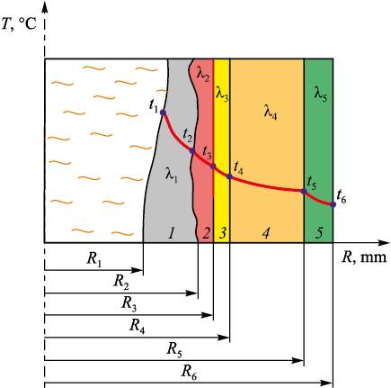
Heat transfer through the five-layer wall was modeled at four specified heights, with known layer thicknesses (e.g., in the region covered by the second refrigerator belt, the layers are shown in Fig. 3).
Fig. 3. Layers of insulating materials in the area of the second belt of refrigerators: |
Due to the degradation of the ceramic cup and insulating material, their actual thicknesses in the temperature control sector (TCS) differ from the design values. The height of the TCS corresponds to the height of the refrigerator. In each horizontal section along the TCS, the temperature of the refractory lining materials varies from point to point, resulting in different degrees of lining erosion (or skull thickness). Each TCS is subdivided into equal-height segments. For each sectional plane, the thickness of all refractory layers is determined, and the temperature distribution across the plane is calculated. Based on the known temperature, the behavior of each layer under increasing or decreasing overall temperature is proportionally estimated.
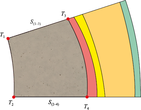
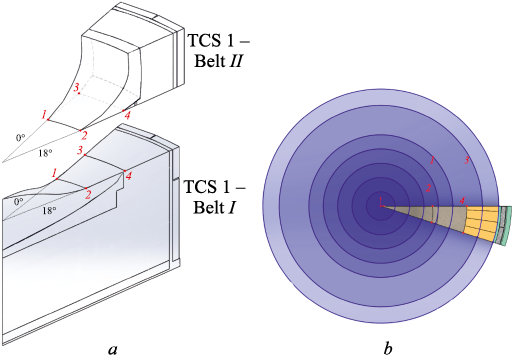
Let us consider the cross-section at a height of 6.5 m (Fig. 4). The thickness of the skull varies in the radial direction (from S(2–4) to S(1–3) ). The coordinates of points T1 and Т2 shift depending on the following conditions:
– if the skull thickness increases, T1 and Т2 move toward the center of the furnace, and the temperature in the sector decreases;
– if the skull thickness decreases, T1 and Т2 shift toward T3 and Т4 , respectively, resulting in a temperature increase.
Fig. 4. Temperature control sector in the 6.5 m plane (bottom view) |
Based on the thermocouple temperatures recorded on the day of the ultrasonic control (USC), reference temperature distributions within the hearth masonry can be determined for all levels.
The thermal conductivity of the skull formation depends on various factors, including its density [22]. In the present calculations, the value of λs = 0.36 W/(m·°C) is assumed.
The Table above presents the input data used for the heat transfer calculations.
Input data for calculation
| |||||||||||||||||||||||||||||||||||||||
Heat conduction through a multilayer planar wall
The bottom of the analyzed blast furnace is composed of seven tightly bonded layers. In the area covered by the first refrigerator belt, the layers (from the inner to the outer surface) are arranged as follows: skull, ceramic layer, super-microporous carbon blocks, carbon blocks, graphite blocks, refractory packing mass, and an air-cooled zone at the bottom, where thermocouples are installed).
The first refrigerator belt is divided by 20 cylindrical cutting planes (Fig. 5, a). The boundary points of skull formation in two refrigerator belts are shown in Fig. 5, b.
Fig. 5. Section by secant cylindrical planes (a) |
Heat transfer through the planar wall is calculated using the surface heat flux density, which is related to the total heat flux by the equation q = Q/F, where F is the surface area of heat exchange.
For a wall composed of n layers, the formula for calculating heat transfer through the planar wall is given by
| \[q = \frac{{{T_1} - {T_2}}}{{\frac{1}{{{\alpha _1}}} + \sum\limits_{i = 1}^n {\frac{{{\delta _i}}}{{{\lambda _i}}} + \frac{1}{{{\alpha _2}}}} }},\] | (6) |
where δi and λi are the thickness and thermal conductivity of the i-th layer of the wall, and Rt is the overall thermal resistance of the multilayer wall, (m2·K)/W.
Then
| \[{R_t} = \frac{1}{{{\alpha _1}}} + \sum\limits_{i = 1}^n {\frac{{{\delta _i}}}{{{\lambda _i}}} + \frac{1}{{{\alpha _2}}}} ;\] | (7) |
| \[q = \frac{{{T_1} - {T_2}}}{{{R_t}}} = \frac{{\sum\limits_{i = 1}^k {\Delta {T_i}} }}{{\sum\limits_{i = 1}^k {{R_{ti}}} }} = {\rm{const}},\] | (8) |
where ΔTi is the temperature drop across the i-th heat transfer section, °C (K); Rti is the thermal resistance of the i-th heat transfer section, (m2·K)/W; k is the number of heat transfer sections.
Visualization of the BF hearth and bottom
Two- and three-dimensional models of the blast furnace hearth are visualized using the Visualization Toolkit (VTK) – an open-source C++ library for modeling, image processing, and applied visualization.
Three-dimensional objects are defined by sets of vertices and faces connecting those vertices. Since these models represent quasi-solids of revolution, the vertex coordinates are specified in a cylindrical coordinate system. The origin of this system is located on an imaginary vertical axis passing through the center of the furnace, starting at elevation 0. However, VTK requires vertex coordinates to be provided in Cartesian coordinates X, Y, Z. Coordinate transformation is performed using the following formulas: X = R cos(A); Y = R sin(A); Z = H.
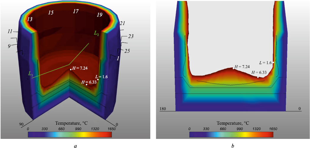
The coordinates of the vertices on the outer surface of the furnace are constant and defined at the model design stage. The inner surface vertex coordinates vary depending on the lining thickness calculated by the hearth burnout mathematical model. The color rendering of the masonry is displayed as a color gradient corresponding to the lining temperature (Fig. 6).
Fig. 6. 3D model of the hearth and bottom (temperature distribution) (a), |
To enhance clarity in the 3D representation of the hearth, any sector can be cut out. This allows for visualization of the internal condition of the lining, with azimuthal section planes freely defined, enabling comprehensive inspection of the entire masonry volume. The cross-section ends are not generated directly by VTK during object slicing; instead, they represent a separate, specially calculated set of points. As a result, each visualization is constructed from four surfaces: the outer surface (constant), the inner surface (model-calculated), and two azimuthal cross-sections (model-calculated).
The accuracy of predicting the remaining thickness of the blast furnace hearth lining is determined by comparing the model results with the findings obtained from ultrasonic control (USC) inspections.
Conclusions
The application of the developed mathematical model enables optimization of the blast furnace smelting process by providing real-time control of the hearth and bottom lining thickness through visual representation. In turn, this opens the way to significant cost reduction through timely decision-making regarding process parameters.
References
1. Chaika A.L., Lebed’ V.V., Sokhatskii A.A., Tsyupa K.S., Kornilov B.V., Shostak V.Yu., Panchokha G.V., Moskalina A.A., Goman S.V., Fomenko A.P. Experience and prospects of complex application of automated control systems for lining burnout, heat losses and heat energy parameters at blast furnaces. Metallurgicheskaya i gornorudnaya promyshlennost'. 2017;(3):2–9. (In Russ.).
2. Pinchuk D.A., Panchokha G.V., Kanaev V.V., Mozharenko N.M. Modern methods of control of residual thickness of the lining of the blast furnace metal receiver. In: Proceedings of the “Fundamental and Applied Problems of Ferrous Metallurgy”. 2005;(11):247–253. (In Russ.).
3. Filatov S.V., Kurunov I.F., Gordon Ya.M., Tikhonov D.N., Grachev S.N. Extension of blast furnace campaign at its intensive operation. Metallurg. 2016;(9):17–22. (In Russ.).
4. Tarakanov A.K., Ivashchenko V.P., Eremin O.O., Sibir A.V., Lyalyuk V.P., Kassim D.A. Control of condition of lining in blast furnace metal receiver. Metallurgicheskaya i gornorudnaya promyshlennost'. 2016;(2):32–38. (In Russ.).
5. Murav’eva I.G., Togobitskaya D.N., Beloshapka E.A., Shumel’chik E.I., Semenov Yu.S. Development of complex criterion for assessment of melts impact on lining in blast furnace metal receiver. In: Proceedings of the “System Technologies”. 2012;(2):79. (In Russ.).
6. Jiao K.-x., Zhang J.-l., Liu Z.-j., Deng Y., Chen C.-l. Cooling phenomena in blast furnace hearth. Journal of Iron and Steel Research International. 2018;25:1010–1016. https://doi.org/10.1007/s42243-018-0160-x
7. Andreev K., Louwerse G., Peeters T., van der Stel J. Blast furnace campaign extension by fundamental understanding of hearth processes. Ironmaking & Steelmaking. 2017;44(2): 81–91. https://doi.org/10.1080/03019233.2016.1154716
8. Liu Z Recent progress on long service life design of Chinese blast furnace hearth. ISIJ International. 2012;52(101): 1713–1723. https://doi.org/10.2355/isijinternational.52.1713
9. Li Y., Chen L., Wang L., Ma J. Monitoring the safety status of a blast furnace hearth using cooling stave heat flux. AIP Advances. 2020;10(2):025308. https://doi.org/10.1063/1.5137827
10. Dmitriev A.N., Chesnokov Yu.A., Chen K., Ivanov O.Yu., Zolotykh M.O. Monitoring system of firebrick lining erosion of blast furnace hearth. IFAC Proceedings Volumes. 2013;46(16):294–301. https://doi.org/10.3182/20130825-4-US-2038.00027
11. Dmitriev A.N., Zolotykh M.O., Vit’kina G.Yu. Monitoring of Condition of Refractory Lining of Blast Furnace Hearth by Digital Technologies. Yekaterinburg: AMB; 2022:154. (In Russ.).
12. Koshelev A.E., Krivolapova L.I., Kravtsova O.A. Method of control of blast furnace hearth lining condition. Pat. 2299910 RU. Applied 07.07.2005; Publ. 27.05.2007. (In Russ.).
13. Torrkulla J., Saxén H. Model of the state of the blast furnace hearth. ISIJ International. 2000;40(5):438–447. https://doi.org/10.2355/isijinternational.40.438
14. Duarte R.M., Ruiz-Bustinza I., Carrascal D., Verdeja L.F., Mochón J., Cores A. Monitoring and control of hearth refractory wear to improve blast furnace operation. Ironmaking & Steelmaking. 2013;40(5):350–359. https://doi.org/10.1179/1743281212Y.0000000045
15. Swartling M., Sundelin B., Tilliander A., Jönsson P.G. Heat transfer modelling of a blast furnace hearth. Steel Research International. 2010;81(3):186–196. https://doi.org/10.1002/srin.200900145
16. Swartling M. A study of the heat flow in the blast furnace hearth lining: Doctoral dissertation. 2010:51.
17. Li Y., Chen L., Ma J. Numerical study on the relationship between the localized depression erosion of a commercial blast furnace hearth lining and the heat flux of cooling staves. IEEE Access. 2019;(7):60984–60994. https://doi.org/10.1109/ACCESS.2019.2915915
18. Swartling M., Sundelin B., Tilliander A., Jönsson P. Experimentally determined temperatures in blast furnace hearth. Ironmaking & Steelmaking. 2010;37(1):21–26. https://doi.org/10.1179/030192309X12506804200627
19. Zhao H., Cheng S. Optimization for the structure of BF hearth bottom and the arrangement of thermal couples. Journal of University of Science and Technology Beijing, Mineral, Metallurgy, Material. 2006;13(6):497–503. https://doi.org/10.1016/S1005-8850(06)60101-1
20. Zhang C., Hou B., Shao L., Zou Z., Saxén H. Estimation of the blast furnace hearth state using an inverse-problem-based wear model. Metals. 2022;12(8):1302. https://doi.org/10.3390/met12081302
21. Dmitriev A.N., Zolotykh M.O., Chen K., Vit’kina G.Yu. Comparative technological analysis of control systems of refractory lining heat-up of blast furnace hearth. Ferrous Metallurgy. Bulletin of Scientific, Technical and Economic Information. 2018;(8):82–91. (In Russ.).
22. Moroz V.F., Togobitskaya D.N., Mozharenko N.M., Nesterov A.S., Bel’kova A.I., Stepanenko D.A. Influence of composition and properties of skull materials on its formation and durability. In: Proceedings of the “Fundamental and Applied Problems of Ferrous Metallurgy”. 2010;22:85–95. (In Russ.).
About the Authors
A. N. DmitrievRussian Federation
Andrei N. Dmitriev, Dr. Sci. (Eng.), Prof., Chief Researcher of the Laboratory of Pyrometallurgy of Reduction Processes
101 Amundsena Str., Yekaterinburg 620016, Russian Federation
D. A. Vit’kin
Russian Federation
Dmitrii A. Vit’kin, Design Engineer
33 Mira Str., Yekaterinburg 620078, Russian Federation
M. O. Zolotykh
Russian Federation
Maksim O. Zolotykh, Cand. Sci. (Eng.), Leading Engineer of Laboratory for Pyrometallurgy of Reduction Processes
101 Amundsena Str., Yekaterinburg 620016, Russian Federation
G. Yu. Vit’kina
Russian Federation
Galina Yu. Vit’kina, Cand. Sci. (Eng.), Leading Researcher, Head of the Laboratory of Pyrometallurgy of Reduction Processes
101 Amundsena Str., Yekaterinburg 620016, Russian Federation
Review
For citations:
Dmitriev A.N., Vit’kin D.A., Zolotykh M.O., Vit’kina G.Yu. Mathematical model of blast furnace hearth condition based on data from thermocouples in refrigerator belts. Izvestiya. Ferrous Metallurgy. 2025;68(3):316-323. https://doi.org/10.17073/0368-0797-2025-3-316-323


