Scroll to:
Mathematical model of the blast furnace main trough lining condition
https://doi.org/10.17073/0368-0797-2025-4-411-416
Abstract
The main trough of a blast furnace represents a complex technological structure that plays a critical role in the ironmaking process by draining molten cast iron and slag from the furnace hearth, thus ensuring the continuity and safety of the process. The reliable operation of the trough directly impacts the blast furnace productivity. The trough must be designed to withstand extremely high temperatures and aggressive chemical environments, and its proper functioning requires constant monitoring and maintenance. Selection of refractory materials and lining technology, as well as the potential for enhancing the resistance of refractory linings in the main mining troughs and extending their service life, are contingent on the timely acquisition of information regarding the thermal load on the refractory layers and casing, the operating conditions, design characteristics, and destruction processes of refractories in interaction with cast iron and slag. The control systems of the blast furnace main mining trough are designed to ensure its safe and efficient operation, by detecting deviations from normal mode in a timely manner and preventing emergency situations. These systems include visual, instrumental and automatic control. The monitoring system of the main mining troughs heat-up will allow the blast furnace technological personnel to control the condition of troughs, estimate their remaining life and make timely decisions on their repair. The developed mathematical model of the blast furnace main trough lining condition takes into account real-time thermocontrol of the blast furnace mining trough casings. It is aimed at obtaining operative information on the main mining troughs heat-up, and is based on the solution of the problem of stationary heat conduction of a multilayer flat wall, each layer of which is a homogeneous wall.
Keywords
For citations:
Dmitriev A.N., Vit’kin D.A., Zolotykh M.O., Vit’kina G.Yu. Mathematical model of the blast furnace main trough lining condition. Izvestiya. Ferrous Metallurgy. 2025;68(4):411-416. https://doi.org/10.17073/0368-0797-2025-4-411-416
Introduction
The blast furnace runner system usually includes a main trough and pouring troughs, with the main trough serving as the location where molten cast iron is separated from slag. Consequently, it operates under the most severe conditions. For this reason, the improvement of its lining receives the greatest attention from both refractory manufacturers and end users.
Available research on heat transfer in the lining of the blast furnace main trough is far more limited compared to studies on the furnace’s internal lining. However, in recent years, information from international publications has made it possible to assess the efforts made to study this issue.
In scientific studies addressing molten cast iron – slag separation in blast furnace main troughs, a wide range of methods has been employed, combining experimental and numerical approaches [1 – 3]. Experimental investigations, such as those reported in [4; 5], relied on physical modeling in which analog fluids (e.g., oil and water to simulate cast iron and slag) were used to examine the influence of trough geometry (inclination angle, cross sectional shape) and tapping velocity on phase separation efficiency. In [5], in particular, a 1:10 scale model was utilized to validate the results of numerical simulations.
Numerical modeling plays a central role in analyzing the complex heat and mass transfer processes in the trough [6 – 9]. Researchers have adopted different numerical approaches, including the finite volume method [7] and the finite element method [8 – 11]), solving the Navier–Stokes equations to describe flow hydrodynamics and the heat conduction equation (with allowance for radiation [11 – 13]) to simulate the temperature field. Key factors influencing separation efficiency and lining service life have been considered, such as flow turbulence [7; 9], heat transfer between the melt and the refractory [14 – 17], thermal radiation [10; 12; 13], and refractory wear [10]. For example, in [7] a k–ε turbulence model was applied, while in [10; 13] nonlocal boundary conditions were introduced to account for thermal radiation. In [8], the authors focused on identifying critical isotherms to extend lining service life, employing a two dimensional heat transfer model and comparing simulation results with experimental data. In [10], it was demonstrated that an adaptive time step regulator could be developed to improve the efficiency of long cycle blast furnace simulations.
In most cases, numerical modeling results showed good agreement with experimental data, making it possible to identify the regions of maximum temperature and stress in the lining [14 – 17] – most frequently in the sidewalls – and to predict its wear. Nevertheless, some uncertainties remain, particularly concerning the precise placement of thermocouples for temperature measurement in an operating trough [18 – 20], which necessitates the use of additional data processing techniques (e.g., the GRSA hybrid algorithm [10]) to refine the results. Overall, the combination of experimental and numerical methods has yielded a more comprehensive understanding of the complex processes occurring in blast furnace main troughs and has provided a foundation for developing recommendations to optimize their design and operation.
Input data
This study is devoted to the development of a mathematical model of the refractory lining of the blast furnace main trough, carried out at the Institute of Metallurgy of the Ural Branch of the Russian Academy of Sciences. An algorithm is presented for calculating the temperature field in the refractory lining of the trough based on thermocouple readings obtained from the outer surface of the trough’s metal casing.
Fig. 1 shows a general (schematic) top view of two blast furnace main troughs.
Fig. 1. Main mining troughs of the blast furnace |
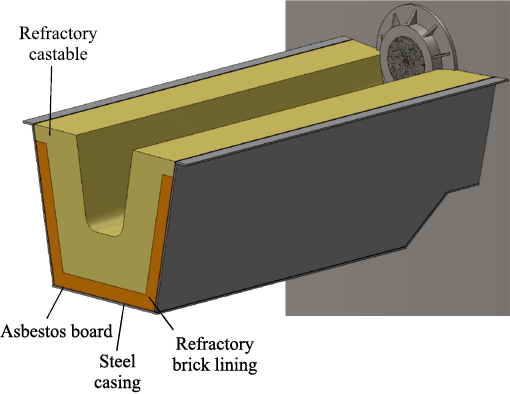
The cross section of the refractory lining of the blast furnace main trough is shown in Fig. 2.
Fig. 2. Main trough lining layers in cross-section |
Calculation of heat conduction through a multilayer flat wall
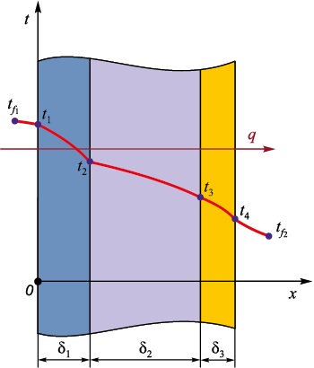
The solution of this problem reduces to steady state heat conduction in a multilayer flat wall, each layer of which is homogeneous. It is assumed that the total thickness of the multilayer wall, equal to the sum of the thicknesses of the individual layers, is much smaller than the wall’s height and width. In this case, the isothermal surfaces are planes parallel to the boundary planes, including the planes of layer interfaces. The individual layers of the wall are assumed to have smooth boundary surfaces that fit tightly together, so that the temperatures of the contacting surfaces are equal (Fig. 3).
Fig. 3. Multilayer flat wall: |
When considering heat conduction in a single layer wall, it is observed that the heat flux density does not change when moving from one isothermal surface to another along the x axis, i.e., from left to right.
The plane of the interface between the first and second layers likewise represents an isothermal surface with the same value of heat flux density as in the first layer. However, this plane serves as the “initial” surface for the second layer, in which a constant heat flux density q, equal to that in the first layer, is also established across the thickness δ2 . The same reasoning applies to all subsequent layers (δ3 , etc.).
The total heat flux, and hence its density, does not vary across the thickness of the multilayer flat wall (Q ≠ f (x) and q ≠ f (x)). Therefore, for any i-th layer of the multilayer flat wall, the following relation holds
| \[{q_s} = \frac{{\Delta {T_i}}}{{\frac{{{\delta _i}}}{{{\lambda _i}}}}} = {\rm{const}}.\] | (1) |
This relation can be expressed sequentially for all layers, beginning with the first:
| \[{q_s} = \frac{{{T_{{f_1}}} - {T_1}}}{{\frac{1}{{{\alpha _1}}}}} = \frac{{{T_1} - {T_2}}}{{\frac{{{\delta _1}}}{{{\lambda _1}}}}} = \frac{{{T_2} - {T_3}}}{{\frac{{{\delta _2}}}{{{\lambda _2}}}}} = \frac{{{T_3} - {T_4}}}{{\frac{{{\delta _3}}}{{{\lambda _3}}}}} = \frac{{{T_4} - {T_{{f_2}}}}}{{\frac{1}{{{\alpha _2}}}}}.\] | (2) |
We then transform the obtained expressions into \(q\frac{1}{{{\alpha _1}}} = {T_{{f_1}}} - {T_2}\) and sum them (combining left-hand sides with left-hand sides and right-hand sides with right-hand sides):
\[q\left( {\frac{1}{{{\alpha _1}}} + \frac{{{\delta _1}}}{{{\lambda _1}}} + \frac{{{\delta _2}}}{{{\lambda _2}}} + \frac{{{\delta _3}}}{{{\lambda _3}}} + \frac{1}{{{\alpha _2}}}} \right) = {T_{{f_1}}} - {T_{{f_2}}}.\]
These derivations remain valid for an arbitrary number of layers. Thus, in the general case, the expression for the surface heat flux density (qs ) is written as:
| \[{q_s} = \frac{{{T_{{f_1}}} - {T_{{f_2}}}}}{{\frac{1}{{{\alpha _1}}} + \sum\limits_{i = 1}^n {\left( {\frac{{{\delta _i}}}{{{\lambda _i}}} + \frac{1}{{{\alpha _2}}}} \right)} }},\] | (3) |
where α1 and α2 are the heat transfer coefficients from the hot fluid to the wall and from the wall to the cold fluid, respectively, W/(m2·K); λ is the thermal conductivity of the material, W/(m·K).
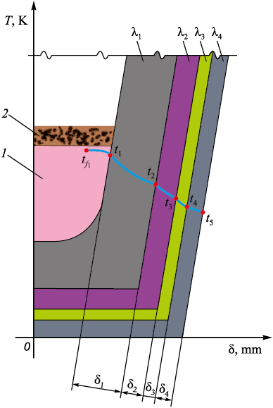
Fig. 4 shows a scheme of heat transfer in the blast furnace main trough.
Fig. 4. Scheme of heat transfer of the main trough: |
Temperature monitoring is performed using thermocouples installed on the casing of the main trough. The lining of the main trough consists of three refractory layers and is enclosed by a steel casing; therefore, in this case, the expression for the surface heat flux density takes the form:
| \[{q_l} = \frac{{{T_{{f_1}}} - {T_5}}}{{\frac{1}{{{\alpha _1}}} + \frac{{{\delta _1}}}{{{\lambda _1}}} + \frac{{{\delta _2}}}{{{\lambda _2}}} + \frac{{{\delta _3}}}{{{\lambda _3}}} + \frac{{{\delta _4}}}{{{\lambda _4}}}}},\] | (4) |
where \({T_{{f_1}}}\) is the temperature of the hot fluid (cast iron, slag), K; Т5 is the casing temperature, measured by a thermocouple (heat removal can be recorded with a sampling interval from 10 s to 24 h), K; α1 is the heat transfer coefficient from the hot fluid to the inner wall of the trough, W/(m2·K); δ1 , δ2 , δ3 , δ4 are the thicknesses of the refractory layers from the innermost to the outermost, m; λ1 , λ2 , λ3 , λ4 are the thermal conductivities of the refractory materials from the innermost to the outermost, W/(m·K).
In the interfacial regions, the thermophysical properties of the materials are averaged.
Block diagram of the calculation algorithm
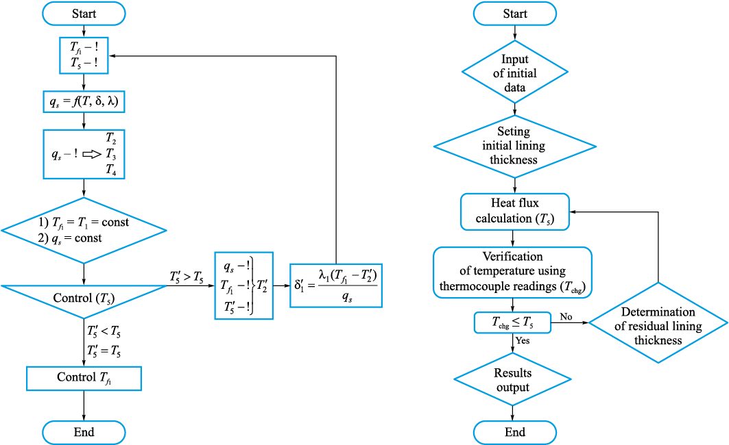
A block diagram of the algorithm for calculating the temperature variation across the lining layers is shown in Fig. 5.
Fig. 5. Block diagram of the algorithm for calculation of temperature change |
Conclusions
The mathematical model developed for the blast furnace main trough lining, based on the solution of the steady state heat conduction problem in a multilayer wall, allows for an efficient evaluation of the thermal load on each refractory layer and the casing in real time (according to the configured heat removal sampling interval). This ensures continuous monitoring of the lining condition, enables prediction of its residual service life (specifically, the thickness of the inner layer), and supports timely decision making regarding repair or replacement. Such capabilities directly enhance the efficiency and safety of blast furnace operation, reduce the risk of emergency situations, and extend the service life of the lining. Future research will aim to further refine the model, for instance by incorporating transient thermal processes (introducing time dependence into the calculations) and by accounting for more complex geometric configurations of the trough.
References
1. Ranjan S., Mazumdar D., Chakraborty I.N., Sinha S., Sarkar R. Review and analysis of metallurgical processes in blast furnace main trough and trough performances. Transactions of the Indian Institute of Metals. 2022;75:589–611. https://doi.org/10.1007/s12666-021-02454-9
2. Kostúr K. Mathematical model for optimisation of a thickness of furnace lining. In: 18th Int. Carpathian Control Conf. (ICCC). 2017:52–57. https://doi.org/10.1109/CarpathianCC.2017.7970370
3. Prompt N., Ouedraogo E. High temperature mechanical characterisation of an alumina refractory concrete for Blast Furnace main trough: Part I. General context. Journal of the European Ceramic Society. 2008;28(15):2859–2865. https://doi.org/10.1016/j.jeurceramsoc.2008.04.031
4. Kim H., Ozturk B., Fruehan R.J. Slag-metal separation in the blast furnace trough. ISIJ International. 1998;38(5):430–439. https://doi.org/10.2355/isijinternational.38.430
5. Monteiro de Oliveira M.J., Rodrigues G., Alves da Silva I., Peixoto J.J.M., da Silva C.A. Modeling of two‐phase flow in blast furnace trough. Steel Research International. 2021;92(3):2000485. https://doi.org/10.1002/srin.202000485
6. Rezende R.V.P., Silva A.F.C., Maliska C.R. The blast furnace trough two-phase flow and its influence in the refractory lining wear: Mathematical modeling and numerical simulation. In: Proceedings of the 19th Int. Congress of Mechanical Engineering. 2007.
7. Ge Y., Li M., Wei H., Liang D. Numerical analysis on velocity and temperature of the fluid in a blast furnace main trough. Processes. 2020;8(2):249. https://doi.org/10.3390/pr8020249
8. Vázquez-Fernández S., Pieiga A.G.L., Lausín-González C., Quintela P. Mathematical modelling and numerical simulation of the heat transfer in a trough of a blast furnace. International Journal of Thermal Sciences. 2019;137:365–374. https://doi.org/10.1016/j.ijthermalsci.2018.11.025
9. Yao H., Chen H., Ge Y., Wei H. Numerical analysis on erosion and optimization of a blast furnace main trough. Materials. 2021;14(17):4851. https://doi.org/10.3390/ma14174851
10. Barral P., Pérez-Pérez L.J., Quintela P. Numerical simulation of the transient heat transfer in a blast furnace main trough during its complete campaign cycle. International Journal of Thermal Sciences. 2022;173:107349. https://doi.org/10.1016/j.ijthermalsci.2021.107349
11. Barral P., Pérez-Pérez L.J., Quintela P. Transient 3D hydrodynamic model of a blast furnace main trough. Engineering Applications of Computational Fluid Mechanics. 2023;17(1):2280776. https://doi.org/10.1080/19942060.2023.2280776
12. Barral P., Nicolás B., Pérez-Pérez L.J., Quintela P. Numerical simulation of wear related problems in a blast furnace runner. Recent Advances in Differential Equations and Applications. 2019;18:229–244. https://doi.org/10.1007/978-3-030-00341-8_14
13. Barral P., Pérez-Pérez L.J., Quintela P. Transient thermal response with nonlocal radiation of a blast furnace main trough. Applied Mathematical Modelling. 2022;105: 197–225. https://doi.org/10.1016/j.apm.2021.12.029
14. Kou M., Yao S., Wu S., Zhou H., Xu J. Effects of blast furnace main trough geometry on the slag-metal separation based on numerical simulation. Steel Research International. 2019;90(2):1800383. https://doi.org/10.1002/srin.201800383
15. Wang L., Pan C.-N., Cheng W.-T. Numerical analysis on flow behavior of molten iron and slag in main trough of blast furnace during tapping process. Advances in Numerical Analysis. 2017;2017(1):713160. https://doi.org/10.1155/2017/6713160
16. Luomala M.J., Paananen T.T., Köykkä M.J., Fabritius J., Matti T., Nevala H., Härkki J.J. Modelling of fluid flows in the blast furnace trough. Steel Research. 2001;72(4): 130–135. https://doi.org/10.1002/srin.200100096
17. He Q., Evans G., Zulli P., Tanzil F., Lee B. Flow characteristics in a blast furnace trough. ISIJ International. 2002;42(8):844–851. https://doi.org/10.2355/isijinternational.42.844
18. He Q., Zulli P., Tanzil F., Lee B., Dunning J., Evans G. Flow characteristics of a blast furnace taphole stream and its effects on trough refractory wear. ISIJ International. 2002;42(3):235–242. https://doi.org/10.2355/isijinternational.42.235
19. Shao L., Saxén H. A simulation study of Blast furnace hearth drainage using a two-phase flow model of the taphole. ISIJ International. 2011;51(2):228–235. https://doi.org/10.2355/isijinternational.51.228
20. Li Z., Wang H., Ding F., Tang H. Prolonging campaign life of blast furnace trough by water cooling. Materials. 2023;16(3):891. https://doi.org/10.3390/ma16030891
About the Authors
A. N. DmitrievRussian Federation
Andrei N. Dmitriev, Dr. Sci. (Eng.), Prof., Chief Researcher of the Laboratory of Pyrometallurgy of Reduction Processes
101 Amundsena Str., Yekaterinburg 620016, Russian Federation
D. A. Vit’kin
Russian Federation
Dmitrii A. Vit’kin, Design Engineer
33 Mira Str., Yekaterinburg 620078, Russian Federation
M. O. Zolotykh
Russian Federation
Maksim O. Zolotykh, Cand. Sci. (Eng.), Leading Engineer of Laboratory for Pyrometallurgy of Reduction Processes
101 Amundsena Str., Yekaterinburg 620016, Russian Federation
G. Yu. Vit’kina
Russian Federation
Galina Yu. Vit’kina, Cand. Sci. (Eng.), Leading Researcher, Head of the Laboratory of Pyrometallurgy of Reduction Processes
101 Amundsena Str., Yekaterinburg 620016, Russian Federation
Supplementary files
Review
For citations:
Dmitriev A.N., Vit’kin D.A., Zolotykh M.O., Vit’kina G.Yu. Mathematical model of the blast furnace main trough lining condition. Izvestiya. Ferrous Metallurgy. 2025;68(4):411-416. https://doi.org/10.17073/0368-0797-2025-4-411-416


