Scroll to:
Development of a continuous extra-furnace steel processing unit
https://doi.org/10.17073/0368-0797-2025-1-98-105
Abstract
The increase in consumption of high-quality steel dictates the need for more steel undergoing the vacuum process, since processing the steel melt under vacuum improves its properties by reducing gas and non-metallic inclusions in it. However, rising fuel prices and the desire to transition to carbon-free metallurgy require the industry to reduce energy intensity and, as a consequence, reduce energy consumption. This can be achieved by switching to continuous production, reducing the period of technological downtime of high-temperature equipment, the temperature of which must be maintained to increase the lining service life and improve the final product quality. But the transition to continuous steelmaking requires the development of a number of new technological units capable of functioning within the framework of the continuous steelmaking unit, including the extra-furnace processing unit for the melt. The propose of the work was development of a theoretical basis for extra-furnace processing unit of molten steel with a continuous degasser. A unit for extra-furnace processing of steel melt with a continuous U-shaped vacuum degasser is presented, which is part of a unit for continuous liquid-phase iron reduction with a capacity of 10 tons per hour for production of St3 steel. The authors studied the influence of residual pressure in a vacuum chamber on the rate of degassing and the time of a gas bubble ascent. Dimensions of the vacuum degasser were determined taking into account the productivity of the iron reduction unit. A multilayer lining was selected, and losses to the environment were assessed, taking into account convective and radiant heat transfer.
Keywords
For citations:
Murashov V.A., Strogonov K.V., Bastynets A.K., Lvov D.D. Development of a continuous extra-furnace steel processing unit. Izvestiya. Ferrous Metallurgy. 2025;68(1):98-105. https://doi.org/10.17073/0368-0797-2025-1-98-105
Introduction
The continuous growth of industrialization and the global population leads to an increase in steel consumption. Over the past 22 years (from 2000 to 2022), global steel production has increased annually by an average of 4 %. Despite a reduction in global steel production in 2023, Russia saw a 5.6 % rise in steel output. In 2023, global steel production reached 1,888 million tons1. With increased production comes increased fuel consumption and environmental emissions, particularly greenhouse gases such as CO2 . The high concentration of CO2 is one of the facto rs contributing to the rise in average surface temperatures on Earth [1; 2]. Therefore, it is important to reduce the energy intensity of steel products, including improving the energy efficiency of steel production.
The transition to continuous production processes, specifically through continuous steelmaking units (CSUs), can reduce specific energy consumption and harmful emissions compared to traditional steel production technologies [3 – 5]. However, the transition to continuous processes requires the development of new components and units capable of operating continuously, including extra-furnace steel processing units.
Extra-furnace steel processing refers to a set of technological operations aimed at producing liquid steel of the required quality, traditionally carried out outside of the steelmaking unit in conventional metallurgy. These processes take place outside the primary unit, thus increasing the productivity of the entire technological chain.
Extra-furnace processing of steel improves the quality of steel, particularly its mechanical properties, corrosion resistance, and other parameters, which is crucial in the production of high-quality steels [6; 7].
The scientific novelty of this work lies in the development of a continuous extra-furnace steel processing unit operating within a CSU, incorporating an alloying zone and a continuous U-shaped vacuum degasser [3]. The study also involves determining the time of gas bubble ascent through analytical and computational methods. The practical significance is focused on reducing the energy intensity of steel during extra-furnace processing, particularly in the vacuum degassing process, improving lining durability by reducing the number of thermal cycles associated with technological downtimes [8], and reducing harmful emissions by lowering exhaust gas output.
Objects and methods of research
The object of development is the extra-furnace steel processing zone, operating within a continuous steelmaking unit (CSU) with a capacity of 10 tons of steel per hour. It consists of two main sections: the deoxidation and alloying zone and the degassing zone.
The deoxidation and alloying processes are essential for achieving the required composition and quality of steel with the necessary strength properties. During extra-furnace processing, elements are introduced in a sequence from weakly oxidizing to strongly oxidizing, considering their affinity for oxygen, which helps to reduce their oxidation losses. For example, manganese oxidation loss can range from 10 to 35 %, silicon from 15 to 25 %, and aluminum from 60 to 90 %.
Based on the state of the elements being introduced, alloying can be categorized into the following: alloying with solid ferroalloys, alloying with liquid ferroalloys, and alloying with exothe rmic ferroalloys.
To determine the list and quantity of elements, it is essential to know the steel grade being produced. The most common steel grade is St3, so the alloying system will be developed for the production of St3.
According to GOST 380–2005 [9] St3 must have the following chemical composition:
– carbon content: 0.14 to 0.22 %;
– manganese content: 0.40 to 0.65 %;
– silicon content: 0.15 to 0.30 %.
Since the vacuum degasser being developed is of continuous operation, a liquid-phase iron reduction unit using natural gas [10] with a reduced capacity of 10 tons per hour can be used as the source of reduced iron. This choice is justified by the existing continuous metal casting system using roll-casting methods. The liquid metal exiting the liquid-phase reduction reactor contains 99.9 % iron [10]. The refore, for the production of St3, taking into account the affinity of elements for oxygen, the following ferroalloy feeding scheme is proposed: initially, ferromanganese is introduced into the stream of liquid metal exiting the reduction unit, followed by the introduction of ferrosilicon during degassing. Based on experience in alloying in traditional metallurgy and the continuous nature of the process, the additives are proposed to be introduced in solid powder form in an argon stream under pressure, similar to calcium.
The reactions taking place are endothermic, so to accelerate the degassing process of the melt, it is recommended to increase the temperature of the liquid steel to approximately 1600 °C before degassing, either by overheating in the reduction reactor or using electrodes installed in the ferromanganese introduction zone.
The amount of alloying component required can be determined using the formula
| \[{G_l} = \frac{{100{G_m}\left( {{E_e} - {E_m}} \right)}}{{{E_l}\left( {100 - {U_e}} \right)}},\] | (1) |
where Gl is the mass flow of the alloying component, kg/s; Gm is the mass flow of the metal, kg/s; Ue is the oxidation loss of the alloying components, %; Ee , Em and El are the alloying component fractions at the end of the process, the beginning of the process, and in the alloying components, respectively.
The oxidation loss of the alloying components is assumed to be around 25 %, and it is proposed to introduce ferromanganese FeMn78(B) and ferrosilicon FeSi90.
After the deoxidation and alloying processes, the steel is transferred to a continuous U-shaped vacuum degasser [11].
For the developed unit, the internal length of the vacuum chamber was set at 1200 mm, considering the expected lining thickness and the need for a constriction.
Based on the unit’s capacity of 10 tons per hour and the vacuum chamber length, the width of the vacuum chamber can be calculated. To do this, the degassing time of the melt must be known. One of the factors determining degassing time is the ascent time of the gas bubble, which depends on its ascent velocity and the height of the melt layer. The bubble ascent velocity in Stokes’ mode (Reynolds number Re < 1) can be determined by the formula (2). For Reynolds numbers from 10 to 1000, it is described by Malenkov’s equation
| \[U = \frac{{2\alpha g\rho {R^2}}}{{9\mu }};\] | (2) |
| \[U = \alpha \sqrt {\beta \frac{{2\sigma }}{{D\rho }} + \frac{{gD}}{2}} ,\] | (3) |
where α and β are numerical constants equal to one in the the oretical derivation; ρ = 7800 kg/m3 is the density of the liquid metal at 1400 °C; R is the radius of the gas bubble; μ = 0.0064 Pa·s is the viscosity of the steel melt; D is the diameter of the gas bubble; and σ = 1.25 is the surface tension coefficient.
Let us assume a characteristic bubble diameter of 1 mm.
Inside the vacuum chamber, a vacuum is created, which will affect the size of the ascending bubble. The change in diameter depending on the vacuum above the melt surface can be determined by the formula
| \[D = {D_0}\sqrt[3]{{\frac{{{P_0}}}{{{P_{{\rm{abs}}}}}}}}\] | (4) |
where D0 = 0.001 m is the characteristic bubble diameter; P0 = 101.3 kPa is the atmospheric pressure above the melt; and Pabs is the absolute pressure above the melt surface.
Once the flow mode is determined, the bubble ascent time can be calculated, taking into account the melt thickness:
| \[\tau = \frac{h}{U},\] | (5) |
where h = 0.4 m is the height of the melt layer, assumed based on methodological recommendations.
According to studies [12; 13], three stages of bubble removal can be distinguished during degassing: gas bubble formation, bubble ascent, and bubble removal from the melt surface.
The degassing time of the liquid metal can be determined using the equation [12 – 14]
| \[\tau = \frac{1}{{{K_{\rm{H}}}}}\ln \left( {\frac{{[\% {{\rm{H}}_{\rm{k}}}] - [\% {{\rm{H}}_{{\rm{eq}}}}]}}{{[\% {{\rm{H}}_{\rm{n}}}] - [\% {{\rm{H}}_{{\rm{eq}}}}]}}} \right),\] | (6) |
where KH = 0.13 min–1 is the hydrogen removal rate constant; [% Hk ] = 1.5 ppm is the final hydrogen concentration (based on industrial practice); [% Hn ] = 6 ppm is the initial hydrogen concentration (based on literature data); and [% Heq ] = 0.8 ppm is the equilibrium hydrogen concentration (Table 1).
Table 1. Equilibrium hydrogen content depending
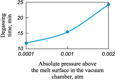
Fig. 1. Dependence of degassing time on pressure |
Fig. 1 shows the graph of the dependence of the extra-furnace steel processing time (degassing) on the absolute pressure in the vacuum chamber, constructed according to equation (6) and data from Table 1.
The width of the vacuum chamber can be determined using the following formula
| \[b = \frac{G}{{Lh\rho }}\tau .\] | (7) |
To ensure a uniform melt flow rate in the degasser and the reduction unit, it is necessary to balance the pressure at points on the same level in the extra-furnace processing zone and at the entrance of the riser pipe in the vacuum chamber. To achieve this, the pressure in the riser pipe must be created by the melt layer. Taking this into account, the height of the riser pipes should be approximately 1.3 m, which is comparable to the dimensions of circulation degasser [15].
Additionally, there should be a clearance between the melt surface and the roof since large bubbles formed during degassing can carry melt droplets, which may damage the lining of the roof.
For ease of maintenance and replacement, the vacuum chamber should be a quick-release component of the extra-furnace processing unit, and it should be equipped with nozzles for introducing alloying elements and inert gas, which are integrated into the riser pipe.
In cases of emergency shutdowns of the steelmaking unit, the design of the degasser must allow for easy drainage of the melt inside the vacuum chamber, which is why the vacuum chamber must have a slope of at least 3°.
To ensure uniform rarefaction in the degasser, it is proposed to have at least two nozzles connected to the vacuum generation system.
Since the developed degasser has a relatively low capacity of about 10 tons per hour, the most efficient solution is to use a vacuum generation system based on mechanical pumps. According to studies [16; 17], using mechanical pumps instead of steam ejector pumps reduces operational costs (variable costs) by at least 80 %. At the same time, capital costs for low-tonnage installations remain at the same level as for systems with steam ejector pumps.
The selection of thermal insulation materials was carried out in accordance with the recommendations from the handbook authored by I.D. Kasheev [18] as well as lining manufacturers 2 and drawings of existing RH-degassers.
Table 2 presents the structure of the vacuum degasser’s fencing elements, including the number of layers, layer thickness, and material. The layers are listed from the inside to the outside.
Table 2. Design of vacuum degasser fencing elements
| |||||||||||||||||||||||
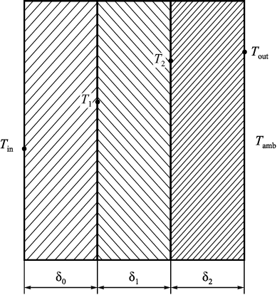
The general design scheme of the fencing structure is shown in Fig. 2.
Fig. 2. Calculation of vacuum degasser lining: |
Taking into account Fig. 2, the integral equation that allows for the determination of the specific heat flux through the fencing structure is as follows:
| \[\begin{array}{c}\frac{1}{{{\delta _0}}}\int\limits_{{t_1}}^{{t_{{\rm{in}}}}} {{\lambda _0}(t)dt} = \frac{1}{{{\delta _1}}}\int\limits_{{t_2}}^{{t_{\rm{1}}}} {{\lambda _1}(t)dt} = \frac{1}{{{\delta _2}}}\int\limits_{{t_{{\rm{out}}}}}^{{t_{\rm{2}}}} {{\lambda _2}(t)dt} = \\ = {\alpha _{{\rm{sum}}}}\left( {{t_{{\rm{out}}}} - {t_{{\rm{core}}}}} \right),\end{array}\] | (8) |
where αsum is the total heat transfer coefficient, considering both convective and radiative heat and mass transfer, measured in W/(m2·°C), and determined by equation (9); λ is the thermal conductivity of the lining material, measured in W/(m·°C), and determined by equation (10); δ is the thickness of the lining layer, measured in meters; and t is the temperature, °C.
| \[{\alpha _{{\rm{sum}}}} = {n_0} + {n_1}{\left( {{t_{{\rm{out}}}} - 20} \right)^{{n_2}}};\] | (9) |
| λ = k0 + k1 t. | (10) |
The coefficients for the equations are presented in Tables 3 and 4.
Table 3. Approximation coefficients ni
Table 4. Properties of fencing materials
|
Results and discussion
According to formula (1), in order to produce steel of the required grade, considering an oxidation loss of alloying elements of approximately 25 %, the following amounts need to be added:
– ferromanganese FeMn78(B) – 11.5 kg/ton;
– ferrosilicon FeSi90 – 2.9 kg/ton.
The manganese content in the steel will be 0.64 %, and the silicon content will be 0.25 %, which meets the requirements for St3 according to GOST [10].
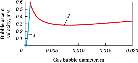
The bubble ascent velocity, calculated using equations (2) and (3) as a function of bubble diameter, is presented in Fig. 3.
Fig. 3. Dependence of bubble ascent velocity |
From the graph, it follows that the critical gas bubble diameter, which satisfies Stokes’ ascent, is 0.1 mm. The refore, the velocity of a bubble with a characteristic size of 1 mm is described by equation (3). Substituting this into equation (4) and using it together with equation (5), we determine that the bubble ascent time is 1.3 s. From this, we can conclude that the gas bubble ascent velocity is not the determining factor in steel degassing. Consequently, according to equation (6) and Fig. 1, the degassing time of the liquid metal will be approximately 15.5 min.
Based on the process time and the capacity of 10 tons per hour, we calculate the width of the vacuum chamber using formula (7), which is 0.7 m.
The specific heat fluxes through various parts of the fencing elements, along with the surface temperature of the vacuum degasser, calculated using formulas (8) – (10), are presented in Table 5.
Table 5. Specific heat flux for fencing elements
|
The obtained values of the specific heat flux are comparable to those for existing RH-degassers, taking into account radiative heat exchange. The specific heat flux for the floor of the vacuum chamber was not determined, as the vacuum chamber floor does not directly contact the surrounding environment.
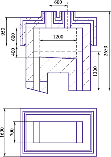
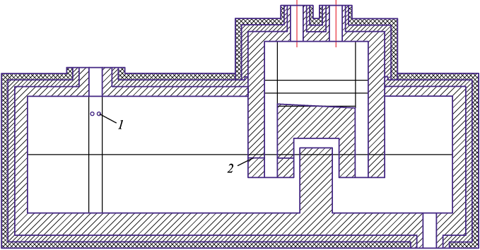
A schematic drawing of the vacuum chamber, considering the previously determined internal dimensions and lining thickness, is shown in Fig. 4.
Fig. 4. Shematic drawing of a vacuum chamber |
According to Fig. 4, the external surface area of the roof will be 3.6 m2, and the surface area of the side walls in contact with the surrounding environment will be 7.8 m2. The refore, the heat loss to the environment will be around 18.2 kW.
A schematic drawing of the extra-furnace processing unit for continuous steel melt degassing is shown in Fig. 5.
Fig. 5. Shematic drawing of an extra-furnace melt processing unit |
The schematic drawings include a system for introducing alloying elements in an argon stream under pressure into the melt stream 1 and a system for blowing inert gas during degassing 2.
Conclusions
Given the annual increase in steel production, including degassed steel, the industry faces the task of improving production efficiency and reducing fuel consumption. Transitioning to continuous processes, as noted in sources [19 – 21] allows for reduced energy consumption in processes and lowers the energy intensity of the final product.
This paper presents a continuous extra-furnace steel processing unit with a capacity of 10 tons of melt per hour, including a U-shaped continuous vacuum degasser. The introduction of alloying elements for St3 steel was considered: ferromanganese is introduced as a powder under pressure into the melt stream during the transfer from the iron reduction zone to the extra-furnace processing zone, and ferrosilicon is introduced into the vacuum degasser together with an inert gas for blowing. The alloying consumption for producing St3 steel from liquid-phase reduced iron will be:
– ferromanganese FeMn78(B) – 11.5 kg/ton;
– ferrosilicon FeSi90 – 2.9 kg/ton.
It is proposed to create a vacuum in the vacuum chamber using mechanical vacuum pumps, as compared to steam ejector systems, capital and operating costs, including energy resource consumption, will be lower.
The degassing time of the melt will be about 15.5 min with a melt layer height of 0.4 m, and the internal width and length of the vacuum chamber will be 0.7 and 1.2 m, respectively. The total heat loss to the environment through the roof and side walls, considering the multilayer lining, will be 18.2 kW, with no losses accounted for through the floor, as it does not contact the surrounding environment. The external surface temperature of the roof will be 122 °C, and the side walls will be 119 °C.
References
1. Ekwurzel B., Boneham J., Dalton M., Heede R., Mera R., Allen M., Frumhoff P. The rise in global atmospheric CO2 , surface temperature, and sea level from emissions traced to major carbon producers. Climatic Change. 2017;144(4): 579–590. https://doi.org/10.1007/s10584-017-1978-0
2. Gordon Y., Kumar S., Freislich M., Yaroshenko Yu. Comparative evaluation of energy efficiency and GHG emissions for alternate iron-and steelmaking process technologies. Творческое наследие В.Е. Грум-Гржимайло: история, современное состояние, будущее. Екатеринбург: Уральский федеральный университет; 2014;1:50–59.
3. Ivantsov G.P., Vasilivitskii A.V., Smirnov V.I. Continuous Steelmaking. Moscow: Metallurgiya; 1967:147 (In Russ.).
4. Strogonov K., Kornilova L., Popov A., Zdarov A. Continuous steelmaking unit of bubbling type. In: Proceedings of the Int. Symp. on Sustainable Energy and Power Engineering 2021. Singapore: Springer Nature Singapore; 2022:63–72.
5. Strogonov K., Borisov A., Murashov V., Lvov D. Calculation of individual elements of enclosing structures of a continuous steelmaking unit. In: 5th Int. Youth Conf. on Radio Electronics, Electrical and Power Engineering (REEPE). IEEE; 2023;(5):1–6.
6. De Paula Lopes B., de Castro J.A., Demuner L.M. A predictive model for hydrogen content in steel in non-degassed heats. Tecnologia em Metalurgia, Materiais e Mineração. 2021;18:e2519. http://dx.doi.org/10.4322/2176-1523.20212519
7. Toirov O., Tursunov N., Alimukhamedov S., Kuchkorov L. Improvement of the out-of-furnace steel treatment for improving its mechanical properties. E3S Web of Conferences. 2023;(365):05002. https://doi.org/10.1051/e3sconf/202336505002
8. Protasov A.V. Domestic developments of equipment and technologies of steel in-line degassing in the process of continuous casting. Ferrous Metallurgy. Bulletin of Scientific, Technical and Economic Information. 2020;76(10): 1004–1012. (In Russ.). https://doi.org/10.32339/0135-5910-2020-10-1004-1012
9. GOST 380-2005. Carbon steel of ordinary quality. Moscow, Interstate Council for Standardization, Metrology and Certification. 2005:16. (In Russ.).
10. Strogonov K.V., Petelin A.L., Terekhova A.Yu., L’vov D.D., Murashov V.A., Borisov A.A. Liquid-phase reduction of iron ores with a carbon-hydrogen mixture and hydrogen. Promyshlennaya ehnergetika. 2023;(8):43–49. (In Russ.). https://doi.org/10.34831/EP.2023.43.83.006
11. Strogonov K.V., Murashov V.A. Continuous steel vacuuming unit. Patent RF no. 2806948. MPK C21С 7/10. Bulleten’ izobretenii. 2023;(31). (In Russ.).
12. Metelkin A.A., Sheshukov O.Yu., Nekrasov I.V., Shevchenko O.I., Korogodskii A.Yu. About hydrogen removal from metal in circular type degasser. Teoriya i tekhnologiya metallurgicheskogo proizvodstva. 2016;(1(18)):29–33. (In Russ.).
13. Korneev S.V. Modern approaches to the removal of hydrogen from steel. In: Metallurgy: Republican Interdepartmental Collection of Scientific Papers. 2018;(39):3–11. (In Russ.).
14. Selivanov V.N., Budanov B.A., Alankin D.V. Kinetic model of hydrogen removal during circulating degassing of steel. Teoriya i tekhnologiya metallurgicheskogo proizvodstva. 2013;(1(13)):31–33. (In Russ.).
15. Dong W., Xu A., Liu B., Zhou H., Ji C., Wang S., Li H., Wang T. Mechanism and model of nitrogen absorption of molten steel during N2 injection process in RH vacuum. Metallurgical and Materials Transactions B. 2024;55(1): 72–82. https://doi.org/10.1007/s11663-023-02937-8
16. Dorstevits F., Tembergen D. Vacuum pump systems for secondary metallurgical processes. Chernye metally. 2013;(9): 37–45. (In Russ.).
17. Burgmann V., Davenet J. The cost structure of steel vacuuming, taking into account the processing in the bucket-furnace unit. Chernye metally. 2012;(11):41–49. (In Russ.).
18. Kashcheev I.D. Properties and Application of Refractories. Moscow: Teplotekhnik; 2004:352. (In Russ.).
19. LIN CS. Analysis of Temperature Dropping of Molten Steel in Ladle for Steelmaking. China Steel Technical Report. 2022;(35):7–12.
20. Polulyakh L.A., Evseev E.G., Savostyanov A.V., Bocherikov R.E. Study of the behavior of phosphorus in the production of manganese alloys using ores with a low manganese content. Metallurgist. 2023;67(10):469–475. https//doi.org/10.1007/s11015-023-01532-1
21. Nurzhanov O.S., Petelin A.L., Nurzhanov A.S., Polulyakh L.A. Analysis of the propagation zone and calculation of concentration fields in the atmosphere of emissions of fine dust from blast furnace No. 4 (PJSC NLMK). Chernye metally. 2022;(9):76–81. (In Russ.). https://doi.org/10.17580/chm.2022.09.12
About the Authors
V. A. MurashovRussian Federation
Viacheslav A. Murashov, Engineer
14 Krasnokazarmennaya Str., Moscow 111250, Russian Federation
K. V. Strogonov
Russian Federation
Konstantin V. Strogonov, Cand. Sci. (Eng.), Assist. Prof. of the Chair of Innovative Technologies of Knowledge-Intensive Industries
14 Krasnokazarmennaya Str., Moscow 111250, Russian Federation
A. K. Bastynets
Russian Federation
Andrey K. Bastynets, Student
14 Krasnokazarmennaya Str., Moscow 111250, Russian Federation
D. D. Lvov
Russian Federation
Dmitry D. Lvov, Postgraduate
14 Krasnokazarmennaya Str., Moscow 111250, Russian Federation
Review
For citations:
Murashov V.A., Strogonov K.V., Bastynets A.K., Lvov D.D. Development of a continuous extra-furnace steel processing unit. Izvestiya. Ferrous Metallurgy. 2025;68(1):98-105. https://doi.org/10.17073/0368-0797-2025-1-98-105
JATS XML


