Scroll to:
Structural-phase composition and mechanical properties of stainless steel – low carbon steel metal composite
https://doi.org/10.17073/0368-0797-2024-6-702-709
Abstract
The subject of the study is a metal composite obtained by electric arc surfacing in argon of corrosion–resistant steel on low-carbon steel. Powdered chromium-nickel steel was deposited with an increased content of silicon and molybdenum relative to the traditional composition. In this work, we studied the elemental and structural-phase compositions, as well as the mechanical properties of both components of the material and the composite as a whole in the initial state and after annealing at 680 °C for 3 h. The main part of the corrosion-resistant component is a two-phase austenitic-ferritic mixture with a ratio of 65 % HCC phase and 30 % BCC phase. The material has high microhardness (more than 4000 MPa). The highest microhardness (4550 MPa) is observed in a narrow strip of deposited metal with a width of 25 μm, where the phase composition is represented by martensite (BCC), and austenite is absent. The transition across the boundary into carbon steel is accompanied by a decrease in microhardness to 1225 MPa. Here, a decarbonized zone with a width of 180 μm was formed near the fusion line. The resulting non-equilibrium stress-strain state of the composite led to low strength, low plasticity and brittle fracture of the deposited layer during tensile testing. After annealing, microstructure of the corrosion-resistant component became more uniform in size of both austenitic and ferritic structural elements. As a result of these transformations, internal stresses decreased and microhardness decreased to 3100 MPa. At the same time, the width of the decarbonized zone in the base metal increased. All these changes led to the fact that, although the tensile stress of the annealed material increased by 8 %, and the deformation to rupture – by 27 %, however, nature of the fracture remained brittle and rupture still occurs along the deposited layer. This is determined by the austenitic-ferritic phase composition of the stainless component, which, in turn, is determined by chemical composition of the deposited material.
Keywords
For citations:
Danilov V.I., Orlova D.V., Shlyakhova G.V., Mironov Yu.P., Petrova E.D. Structural-phase composition and mechanical properties of stainless steel – low carbon steel metal composite. Izvestiya. Ferrous Metallurgy. 2024;67(6):702-709. https://doi.org/10.17073/0368-0797-2024-6-702-709
Introduction
The strict and often contradictory requirements for materials in specialized mechanical engineering, chemical, nuclear, electrical, and electronics industries frequently make it impossible to rely on existing homogeneous metals and alloys. This challenge has driven the development and widespread adoption of layered metal composites. These composites, widely used in mechanical engineering, are valued for their high structural strength, corrosion resistance, heat resistance, and weldability – all achieved at relatively low cost. In large-scale industrial production, layered metal composites are typically manufactured as sheets, tubes, strips, and rods through casting followed by joint hot rolling of the components [1 – 4]. For applications with limited production volumes, various protective coatings – such as gas-thermal, ion-plasma diffusion, or electroplated coatings – are often more practical [5 – 8].
Among the most commonly used layered metal composites are those featuring a base layer of low-carbon or low-alloy steel, with cladding layers made of corrosion-resistant steel, copper, nickel, titanium, or other metals and alloys. This combination is designed to ensure that the base layer provides the required strength characteristics, while the cladding layer protects against aggressive environmental conditions. A cost-effective and accessible method for producing such composites is electric arc surfacing using a consumable austenitic electrode applied to low-alloy carbon steel [9]. This method makes it possible to create cladding layers with the desired physical and mechanical properties and precise geometric parameters. The use of powdered electrodes has proven particularly effective [10; 11]. Moreover, the process is compatible with standard welding machines, leveraging well-established operating modes [12].
Despite its advantages, the production of such metal composites is not without challenges. Issues such as residual stresses, anisotropy, and the formation of porosity remain significant concerns. It is well known that during surfacing or welding, the cladding layer can acquire either a cast structure (in single-layer surfacing) or a structure modified by additional thermal treatment in specific zones (in multi-pass surfacing). When corrosion-resistant steel is surfaced onto carbon steel, the fusion zone may form martensitic or austenitic-ferritic structures, depending on the carbon content and diffusion processes [13 – 15]. Insufficient nickel and chromium in the deposited metal can lead to a secondary austenitic-martensitic structure [12]. These structures inevitably contribute to a complex stress state in and around the contact zone. Furthermore, the degree of mixing between the base and deposited metals significantly influences the stress-strain state of the bimetal composite. Ultimately, these factors play a decisive role in determining the overall performance characteristics of the layered metal composite.
This study aimed to assess the structure and stress-strain state of a layered metal composite made from corrosion-resistant steel and low-carbon steel, produced via electric arc surfacing, and to identify optimal thermal treatment parameters to enhance the structural strength of the material.
Materials and methods
The subject of this study is a metal composite obtained through automatic electric arc surfacing in an argon atmosphere, performed in two passes using a consumable powdered electrode on a plate of standard carbon steel grade 20 (as per GOST 1050–88) [16]. The electrode diameter was 1.5 mm, the plate thickness was 8 mm, the width of the deposited bead was 20 mm, and the average bead height was 10 mm. The chemical composition of the powdered electrode was as follows (wt. %: ≤0.12 С; ~18.0 Cr; ~1.0 Mn; ~5.0 Si; ~9.0 Ni; ~1.0 Mo; ~0.2 Ti; <0.04 S; <0.04 P; with the balance being iron. To prevent cracking during surfacing, the plate was preheated to approximately 300 °C.
For mechanical testing, a series of “dog bone” samples were cut from the resulting workpiece along the axis of the bead using the electro-erosion method.
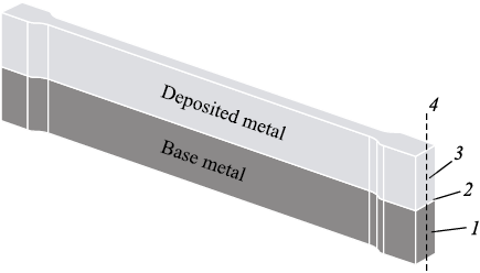
The sample design and the scheme for measuring microhardness and evaluating structural-phase characteristics are shown in Fig. 1. The dimensions of the working section of the sample were 40×6×2 mm. In the working area of the sample, the fractions of the deposited metal and the base metal were approximately equal. Some of the prepared samples were annealed in a vacuum at a temperature of 680 °C for 3 h, followed by furnace cooling (the initial state of the samples without heat treatment is referred to as “State 1” and the state after annealing is referred to as “State 2”). For structural analysis, cross-sectional samples were prepared in accordance with RD 24.200.04–90. The analysis of the cross-sections was conducted using a Neophot-21 microscope (Zeiss, Germany). The elemental composition of the deposited and base metals was determined using a LEO EVO 50 scanning electron microscope (Zeiss, Germany). Microhardness was measured with a PMT-3 microhardness tester (1 N load on the indenter), and phase composition was analyzed with a DRON-8 X-ray diffractometer (copper radiation).
Fig. 1. A sample of metal composite for mechanical testing and determination |
Uniaxial tensile tests at room temperature were conducted on a Walter + Bai AG, model LFM-125 machine (Switzerland) at a crosshead speed of 0.2 mm/min.
Results and discussion
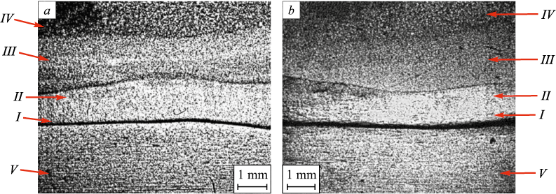
Fig. 2, a shows the macrostructure of the metal composite sample in State 1. A strongly etched fusion boundary is distinctly visible. The deposited metal exhibits a layered structure with well-defined boundaries (Fig. 2, a). The layers are numbered starting from the fusion boundary, and their dimensions are provided in Table 1.
Fig. 2. Macrostructural image of the metal composite:
Table 1. Layers of deposited metal
| ||||||||||||||||||||||
Layer I is located immediately adjacent to the fusion line, where the deposited metal underwent the most significant structural and phase transformations. The material in this layer etches poorly, giving it an unstructured appearance. The formation of such “white zones” is typical for welded joints between high-alloy corrosion-resistant steels and carbon steels. According to previous studies [17 – 19], these zones exhibit a martensitic structure. In the macroscopic image (Fig. 2, a), layers II and III appear visually similar but are separated by a clearly distinguishable boundary.
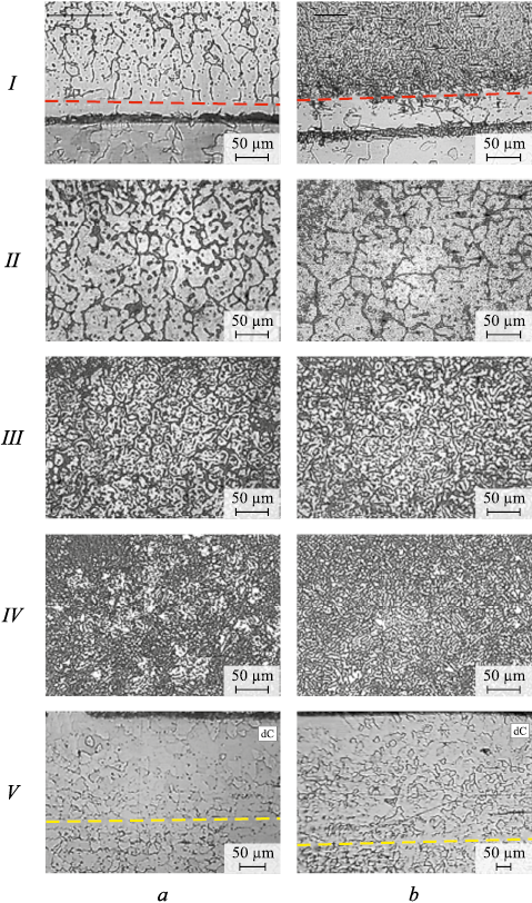
Microstructural analysis revealed that in State 1, the deposited metal has a cast structure, with the size and morphology of structural elements differing across layers II – IV (Fig. 3, a). In layers II and III, the deposited metal displays a dendritic structure with dark inter-dendritic regions. Near the boundary between layers I and II, the dendrites transition into polyhedral grains, while the inter-dendritic regions transform into inter-granular boundaries. The boundary of layer I is marked with a red dashed line in Fig. 3. As the boundary of layer III is approached, the thickness of the inter-dendritic regions increases, the transverse size of the dendrites decreases, and dark particles begin to form within them. Overall, in layer III, the dendritic structure is most pronounced and relatively uniform. The structure of layer IV is heterogeneous. The transverse sizes of the dendrites can vary significantly, differing by several times. The dark regions between the dendrites are spatially oriented and appear to have a phase composition distinct from that of the dendrites themselves.
Fig. 3. Microstructure in layers I – IV of the deposited metal and base metal V: |
Figs. 2, a and 3, a show that the macro- and microstructure of the base metal (layer V) is generally typical. The microstructure corresponds to that of high-quality carbon steel grade 20, consisting of polyhedral ferrite grains with a small amount of pearlite (Fig. 3, a). In State 1, the average grain size was 21 ± 5 µm, corresponding to a grain size number of 8 ÷ 9. Notable structural changes were observed near the fusion line, where a decarbonized zone (dC) formed, characterized by the absence of pearlite. This zone is 180 µm wide, with its boundary indicated by a yellow dashed line in Fig. 3.
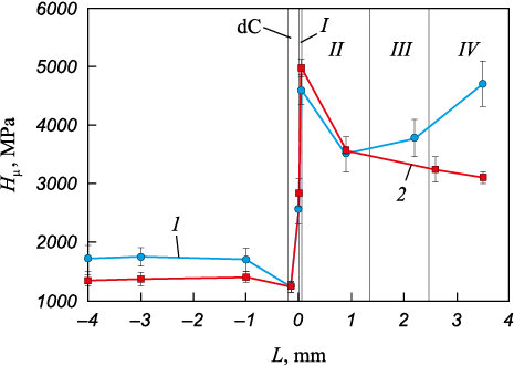
The microhardness of the composite varies according to the structural characteristics of its layers (Fig. 4, curve 1). The deposited metal exhibits a microhardness more than double that of the base metal, approximately 4000 MPa compared to 1700 MPa. The highest microhardness, 4550 MPa, is observed in the non-etching layer I. Moving toward the middle of layer II, the microhardness decreases but begins to rise again, reaching a nominal value of about 4000 MPa in layer III. At the fusion boundary, the microhardness measures 2550 MPa, while its lowest value of 1225 MPa corresponds to the decarbonized zone (dC) in the base metal.
Fig. 4. Microhardness in different layers of the metal composite |
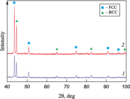
The structural characteristics of the deposited metal layers and the microhardness distribution are closely tied to changes in phase composition. Fig. 5 shows the diffraction pattern obtained for the main portion of the deposited metal (curve 1), indicating the presence of two dominant phases: FCC and BCC. At the farthest distance from the fusion boundary (layer IV), the FCC phase (~65 %, austenite) predominates, while the BCC phase (ferrite) makes up no more 30 %, with no signs of tetragonal distortions. In Fig. 3, a, the bright structural elements in layer IV are identified as austenite, while the darker, oriented features correspond to ferrite. The remaining ~5 % of the volume consists of a mixture of low-symmetry phases, silicides, and carbides. Near the fusion boundary, the phase composition reverses: in layer I, the BCC phase dominates, while austenite accounts for no more than 5 % of the volume and exhibits significant texturing. The proportion of low-symmetry phases also decreases to around 2 %. As expected, the base metal consists primarily of the BCC phase. However, near the fusion boundary, the 220 diffraction peaks exhibit significant broadening, likely caused by tetragonal lattice distortions and internal stresses. This observation aligns with previous studies [17; 18] which describe a martensitic structure in the non-etching zone near the fusion boundary.
Fig. 5. X-ray diffraction patterns of the deposited layer |
The observed structural-phase characteristics and microhardness distribution are driven by the diffusion-driven redistribution of carbon and alloying elements near the fusion line (between the base and deposited metals). This is supported by the results of elemental analysis (Table 2).
Table 2. Chemical composition of the deposited metal
| |||||||||||||||||||||||||||
In layers III and IV of the deposited metal, the alloying element content closely matches the chemical composition of the powdered electrode. Using the concepts of Creq and Nieq and the A. Schaeffler structural diagram for chromium-nickel stainless steels [20], the two-phase structure of these layers becomes clear. According to this diagram, the FCC phase corresponds to austenite, while the BCC phase corresponds to ferrite. In layer II, the nickel content decreases by a factor of three, silicon content by nearly half, and chromium content by half. As a result, the phase composition is a mixture of martensite and austenite, consistent with microstructural analysis findings. In layer I, the chromium and silicon content drops by a factor of three, and the nickel content decreases by a factor of 5.5, leaving only martensite. This result aligns with both microstructural observations and X-ray diffraction analysis.
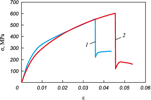
The analysis of structure, microhardness, X-ray diffraction, and elemental composition in the initial State 1 reveals a significant heterogeneity in the material’s stress-strain state, which adversely affects the composite’s structural strength. The stress-strain curve from uniaxial tensile testing is shown in Fig. 6 (curve 1). The material displays low plasticity, which is unusual for both carbon and stainless steels. At a strain of ε = 3.6 %, the deposited layer fails, forming a crack that extends through the entire layer. The crack opening reaches up to 1 mm. The diagram shows that the stress calculated for the full cross-section of the composite drops from 554.2 to 219.5 MPa. The base metal layer remains intact and continues to deform plastically. The remaining undamaged cross-sectional area of the sample is 6.33 mm2, meaning that the stress acting in this area equals the stress in the entire sample at the moment the crack forms. This indicates that the failure of the deposited layer is brittle. The low fracture toughness of the deposited layer is likely due to high internal stresses. This issue can be addressed by annealing, which, as described earlier, was performed for 3 h at 680 °С.
Fig. 6. Loading curves for the composite in initial state (1) |
The macroscopic image of the annealed material (Fig. 2, b) shows that the layered structure of the deposited metal is largely preserved, although the boundary between layers III and IV is noticeably blurred. The width of layer I has increased to 50 µm (Table 1). Layer I remains non-etching (Fig. 3, b). The adjacent layer II, as in State 1, exhibits a grain structure that gradually transitions into a dendritic structure. The evolution of the microstructure from layer II to layer III after annealing follows the same pattern observed in the initial state. The dendritic structure of layer III remains unchanged between the initial and annealed states. However, significant changes occur in the microstructure of layer IV (Figs. 3, a and 3, b). The microstructure becomes more uniform, with the bright austenitic structural elements becoming more consistent in size, while the dark ferritic elements thicken and lose their preferred orientation.
The microhardness distribution of the composite after annealing (State 2) is shown in Fig. 4, curve 2. The most notable changes are observed in layer IV, where the microhardness decreases from 4700 to 3100 MPa. Conversely, the microhardness of layer I increases by 400 MPa compared to the initial state, while the microhardness of the base metal shows a slight decrease. It is also noteworthy that, while the microhardness of the decarbonized zone remains unchanged after annealing, the width of this zone expands to approximately 500 µm.
The phase composition in layers III and IV remains unchanged after annealing (Fig. 5, b), consisting of austenite, ferrite, and less than 5 % of low-symmetry phases. The half-width of the main peaks for the BCC and FCC phases decreases compared to the initial state, indicating a reduction in second-order internal stresses. Furthermore, in layer I, the content of the FCC phase decreases significantly (to about 2 %), and the proportion of low-symmetry phases drops to less than 2 %. After annealing, the base metal consists of a more refined BCC phase, reflecting the absence of elastic distortions.
Overall, the deposited metal, fusion boundary, and the composite as a whole transition to a more equilibrated stress-strain state, which has a positive effect on the material’s structural strength. As shown by curve 2 in Fig. 6, while the deposited metal still fractures in a brittle manner, the tensile stress at failure increases to 603 MPa, and the relative elongation improves to 4.56 %.
Conclusions
Studies of the composite produced by electric arc surfacing in an argon atmosphere, combining stainless steel and low-carbon structural steel, showed that the corrosion-resistant component has a two-phase austenitic-ferritic structure. The component features a dendritic structure, with an elemental composition matching that of the electrode wire. The ferritic phase is concentrated in the inter-dendritic regions. Closer to the fusion boundary, the dendritic structure transitions into a grain structure, and the FCC phase content decreases to zero. At the same time, the concentration of alloying elements drops by a factor of 3 to 5, resulting in the formation of a martensitic structure within a few micrometers of the fusion boundary. Overall, the deposited layer exhibits high hardness and brittleness due to significant internal stresses. Annealing at 680 °C for 3 h improves the microstructure of the deposited layer, reduces hardness, and increases relative elongation at failure. However, the composite remains brittle.
During electric arc surfacing of the corrosion-resistant layer onto low-carbon steel grade 20, a porosity-free layer is formed that is strongly bonded to the base metal. This layer exhibits an austenitic-ferritic phase composition with substantial internal stresses, leading to brittle fracture under load. This brittleness is attributed to the elevated silicon and molybdenum content in the powdered electrode wire compared to traditional compositions for chromium-nickel stainless steels. Although annealing relieves internal stresses in the deposited layer, it does not fully eliminate the composite’s brittleness.
References
1. Golovanenko S.A., Meandrov L.V. Bimetal Production. Moscow: Metallurgiya; 1966:297. (In Russ.).
2. Dhib Z., Guermazi N., Gaspérini M., Haddar N. Cladding of low-carbon steel to austenitic stainless steel by hot-roll bonding: Microstructure and mechanical properties before and after welding. Materials Science and Engineering: A. 2016;656:130–141. http://doi.org/10.1016/j.msea.2015.12.088
3. Hu K., Xia Y., Zhu F., Noda N.A. Evaluation of thermal breakage in bimetallic work roll considering heat treated residual stress combined with thermal stress during hot rolling. Steel Research International. 2017;89(4):1700368. http://doi.org/10.1002/srin.201700368
4. Mittler T., Greb T., Feistle M., Krinninger M., Hofmann U., Riedle J., Golle R., Volk W. Fabrication and processing of metallurgically bonded copper bimetal sheets. Journal of Materials Processing Technology. 2019;263:33–41. https://doi.org/10.1016/j.jmatprotec.2018.08.008
5. Hocking M.G., Vasantasree V., Sidky P.S. Metallic and Ceramic Coatings. NY: Longman Scientific & Technical Publisher; 1989:670.
6. Khmelevskaya V.B., Moseiko E.S., Ol’khovik E.O. Study of strengthening of ship propeller parts by plasma spray coating with ultrasonic treatment. Vestnik gosudarstvennogo universiteta morskogo i rechnogo flota im. admirala S.O. Makarova. 2013;(3):81–87. (In Russ.).
7. Monceau D., Oquab D., Estournes C., Boidot M., Selezneff S., Ratel-Ramond N. Thermal barrier systems and multi-layered coatings fabricated by spark plasma sintering for the protection of Ni-base superalloys. Materials Science Forum. 2010;654–656:1826–1831. https://doi.org/10.4028/www.scientific.net/MSF.654-656.1826
8. Gotz W., Heinisch T. Leyendecker: Steckverbinder – Hohe Zuverlässigkeit bei reduziertem Edelmetalleinsatz. Galvanotechnik. 2003;4(9):2139–2140. (In Germ.).
9. Bandyopadhyay A., Heer B. Additive manufacturing of multi-material structures. Materials Science and Engineering: R: Reports. 2018;129:1–16. https://doi.org/10.1016/j.mser.2018.04.001
10. Kozyrev N.A., Kibko N.V., Umanskii A.A., Titov D.A. Improving the quality of deposited layer of rolling rolls by optimizing the composition of flux-cored wires. Svarochnoe proizvodstvo. 2017;7:29–34. (In Russ.).
11. Usol’tsev A.A., Kozyrev N.A., Bashchenko L.P., Kryukov R.E., Zhukov A.V. Development of flux-cored wire of Fe – C – Si – Mn – Cr – W – V system with additives of carbon-fluorine-containing material and titanium. Izvestiya. Ferrous Metallurgy. 2023;66(4):403–409. https://doi.org/10.17073/0368-0797-2023-4-403-409
12. Sidorov V.P., Mel’zitdinova A.V. Methodology for determining the requirements for welding parameters accuracy. Svarka i diagnostika. 2014;(3):10–13. (In Russ.).
13. Boronenkov V.N., Korobov Yu.S. Basics of Arc Metallization. Physico-Chemical Patterns. Ekaterinburg: Izd. Ural. un-ta; 2012:268. (In Russ.).
14. Zernin E.A., Petrova E.D., Danilov V.I., Shlyakhova G.V. Structure and properties of a metal deposited by a powder wire in a plasma stream. Svarka i diagnostika. 2024;(2):28–33. (In Russ.). https://doi.org/10.52177/2071-5234_2024_02_28
15. Wielage B., Pokhmurska H., Student M., Gvozdeckii V., Stupnyckyj T., Pokhmurskii V. Iron-based coatings arc-sprayed with cored wires for applications at elevated temperatures. Surface & Coatings Technology. 2013; 220:27–35. https://doi.org/10.1016/j.surfcoat.2012.12.013
16. Sorokin V.G., etc. Steels and Alloys. Grade Guide: Reference Book. Moscow: Intermet Inzhiniring; 2001:608. (In Russ.).
17. Gel’man A.S., Chudnovskii A.D., Tsemakhovich B.D., Kharin I.L. Cladding of Steel by Explosion. Moscow: Mashinostroenie; 1978:191. (In Russ.).
18. Trudov A.F., Trykov Yu.P., Klochkov S.V., Dontsov D.Yu., Voinov M.O. The effect of heat treatment on the structural and mechanical heterogeneity of explosion-welded bimetal St.3+12Kh18N10T. Deformatsiya i razrushenie materialov. 2009;12:41–44. (In Russ.).
19. Shlyakhova G.V., Barannikova S.A., Bochkareva A.V., Li Yu.V., Zuev L.B. Study of the structure of bimetal construction carbon steel – stainless steel. Izvestiya. Ferrous Metallurgy. 2018;61(4):219–223. (In Russ.). https://doi.org/10.17073/0368-0797-2018-4-300-305
20. Schaeffler M. Constitution diagram for stainless steel weld metal. Metal Progress. 1949:56:680–681.
About the Authors
V. I. DanilovRussian Federation
Vladimir I. Danilov, Dr. Sci. (Phys.-Math.), Prof., Chief Researcher of the Laboratory of Strength Physics
2/4 Akademicheskii Ave., Tomsk 634055, Russian Federation
D. V. Orlova
Russian Federation
Dina V. Orlova, Cand. Sci. (Phys.-Math.), Research Associate of the Laboratory of Strength Physics
2/4 Akademicheskii Ave., Tomsk 634055, Russian Federation
G. V. Shlyakhova
Russian Federation
Galina V. Shlyakhova, Cand. Sci. (Eng.), Research Associate of the Laboratory of Strength Physics
2/4 Akademicheskii Ave., Tomsk 634055, Russian Federation
Yu. P. Mironov
Russian Federation
Yurii P. Mironov, Cand. Sci. (Phys.-Math.), Research Associate of the Laboratory of Materials Science of Shape Memory Alloys
2/4 Akademicheskii Ave., Tomsk 634055, Russian Federation
E. D. Petrova
Russian Federation
Ekaterina D. Petrova, Assistant of the Chair of Welding of Ship Structures
3 Lotsmanskaya Str., St. Petersburg 190121, Russian Federation
Review
For citations:
Danilov V.I., Orlova D.V., Shlyakhova G.V., Mironov Yu.P., Petrova E.D. Structural-phase composition and mechanical properties of stainless steel – low carbon steel metal composite. Izvestiya. Ferrous Metallurgy. 2024;67(6):702-709. https://doi.org/10.17073/0368-0797-2024-6-702-709


