Scroll to:
Assessment of the effectiveness of technological measures to extend the campaign of blast furnace No. 5 of PJSC Severstal (2006 – 2024) based on an examination of its working space during a first-category overhaul
https://doi.org/10.17073/0368-0797-2024-5-520-530
Abstract
The paper presents the findings from the study of the working space of blast furnace No. 5 of PJSC Severstal during its first-category overhaul in 2024 lasting 17.46 years, which significantly exceeded the standard service life. The effectiveness of technological measures taken to extend the furnace’s campaign from 2006 to 2024, aimed at protecting the refractory lining in critical areas such as the hearth, lower shaft, and the upper bosh, was evaluated. The residual thickness of the refractory lining in the shaft, hearth, and metal receiver is analyzed, and maps showing the actual thickness of the lining across different sections are generated. The measured maximum wear of the shaft refractory lining is 344 mm (37.4 % of the original value); the measured maximum wear of carbon blocks in the area of cesspool openings – 313 mm (23.4 % of the original block size). In the upper part of the hearth, the minimum residual thickness of refractories with an Al2O3 content of 43 % is 220 mm or 31.9 % of the initial value. The paper also discusses safe remote measurement methods, including 3D laser scanning of the furnace shaft during the removal of residual charge materials. It highlights the advantages of ground-based laser scanners in capturing dense, high-quality 3D geometric data. Additionally, the paper describes the experience of remotely measuring the residual thickness of carbon blocks around the raking openings. Comparisons are made between the actual residual thickness of the refractory lining in the hearth, bottom carbon blocks, and high-alumina refractories of the tuyere zone, and the results obtained using ultrasonic echo-sounding technology (AU-E) during the furnace’s operation. The paper also includes a description of the stress wave propagation technology, which utilizes data analysis in the time and frequency domains to determine lining thickness and detect anomalies. The results of the current and previous blast furnace campaigns are compared in terms of pig iron production, the number of cooling system failures, and refractory wear across the entire working space of the furnace. The total production of pig iron in the 2006 – 2024 campaign, related to the furnace area, amounted to 420.0 thousand tons/m2 and exceeded the figure for the previous campaign by 1.90 times.
Keywords
For citations:
Kal’ko A.A., Leont’ev L.I., Volkov E.A. Assessment of the effectiveness of technological measures to extend the campaign of blast furnace No. 5 of PJSC Severstal (2006 – 2024) based on an examination of its working space during a first-category overhaul. Izvestiya. Ferrous Metallurgy. 2024;67(5):520-530. https://doi.org/10.17073/0368-0797-2024-5-520-530
Introduction
The extension of a blast furnace (BF) campaign, defined as the period between first-category overhauls, allows for a reduction in the cost of pig iron production. To increase the length of the inter-repair period, both technical and technological measures are developed. The effectiveness of these measures is generally evaluated based on the results of the completed campaign, taking into account its duration and the volume of pig iron produced during the inter-repair period. The end of the campaign is primarily determined by reaching the minimum permissible residual thickness of the refractory lining. Many researchers [1 – 4] have noted that the achievement of a long, safe, and accident-free operation of the blast furnace largely depends on the durability of the hearth and the bottom. While the residual thickness of the shaft lining can be measured periodically during brief furnace shutdowns when the charge level is lowered, direct measurements of the refractory thicknesses in the hearth and bottom during the campaign are extremely difficult, and wear assessment can only be performed using non-destructive testing methods [5]. This makes the information about the actual condition of the refractories in the working space of the furnace, obtained during a shutdown for re-lining, usually during a first-category overhaul, particularly valuable. Such information not only allows for the evaluation of the adequacy of non-destructive testing methods and the calculation models used during the campaign to assess the lining thickness, but also helps identify critical areas requiring protection and adjustments to the smelting technology in the future.
This paper presents the experience of studying the working space of blast furnace No. 5 of PJSC Severstal during its first-category overhaul in 2024. The furnace operated in its campaign from October 20, 2006, to April 2, 2024, for a total of 17.46 years (referred to as the current campaign hereinafter), significantly exceeding the standard service life typical for blast furnaces of similar design. During the campaign, over 75 million tons of pig iron were produced, surpassing the cumulative pig iron output of the first two campaigns. These results were achieved on a blast furnace of “classic” design, without any major capital-intensive changes to the refractory lining of the shaft and hearth, but through the development of new methods for managing, controlling, and adjusting the pig iron smelting technology [6].
Предпосылки проведения исследований
Based on the results of the study of the working space of blast furnace No. 5, which was blown out at the end of the previous campaign (1995 – 2006), certain zones requiring protection and adjustments to the smelting technology for the current campaign (2006 – 2024) were identified. These were the hearth, the lower shaft, and the upper bosh, as the zones were found to have low residual refractory thickness and little to no protective skull.
In the current campaign, a set of measures was implemented, including regular hearth washing to remove coke debris and flux residues, maintaining a stable self-renewing skull in the lower shaft, and ensuring effective distribution of different types of solid fuel across the furnace’s cross-section, as described in detail in [6]. The need to assess the effectiveness of these measures formed the basis for launching a program to study the working space of blast furnace No. 5 during its 2024 overhaul. It should be noted that blast furnace No. 5 accounts for up to 40 % of the total pig iron production at PJSC Severstal, imposing strict time constraints on the repair schedule and the duration of any studies aimed at extending this timeframe. Based on this premise, it was decided to minimize human presence during measurements in the working space of the furnace and to maximize the use of modern remote measurement methods with laser scanners.
Measurement of actual lining wear in the shaft of BF No. 5 using the Leica RTC360 scanner
Ground-based laser scanners (GLS) are instruments capable of quickly capturing dense, high-quality 3D geometric data of the surrounding environment. They have become standard tools in numerous applications, such as as-built modeling, environmental and geological sciences, forensic analysis, and engineering. Photogrammetry and geodesy, being engineering disciplines with the highest accuracy requirements, have recently driven significant improvements in this measurement technology, making it competitive even for the most complex measurement tasks [7].
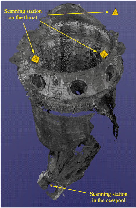
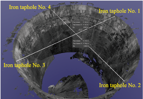
The scanning was performed on April 12, 2024, during the furnace raking process, using the Leica RTC360 scanner. Measurements were taken from the throat platform at three points and from the cesspool area at the casthouse level. The results of the scan yielded a point cloud consisting of 117.5 million points. The points were processed using Leica TruView software. Due to the limitations of direct visibility to all sections of the furnace’s inner surface, some areas were partially not covered by the scan. The overall view of the measured point cloud, representing the inner surface of the blast furnace and the location of the scanning stations, is shown in Fig. 1. Measurements of the actual internal diameters of the furnace at various levels were taken at heights of +43,900 mm, +41,350 mm, +40,500 mm, +39,500 mm, +38,500 mm, +37,500 mm, +36,500 mm, +35,500 mm, +34,500 mm, +33,500 mm, and +32,500 mm. Horizontal sections of the scanning areas at the corresponding heights were used to determine these diameters. An example of a diameter measurement at +43,900 mm, with reference to the location of the tap holes, is shown in Fig. 2.
Fig. 1. General view of the scanning results of the internal space
Fig. 2. Example of measuring the diameter of the internal space |
Additionally, orthogonal projections of the scanning results were constructed with a 1 m step and an initial offset of 0.5 m from the aforementioned height levels (from +43,000 mm to +32,000 mm inclusive), which made it possible to create a map of the actual wear of the refractory lining in the shaft of blast furnace No. 5, as shown in Table 1.
Table 1. Actual wear of the refractory lining in the shaft of blast furnace No. 5
| ||||||||||||||||||||||||||||||||||||||||||||||||||||||||||||||||||||||||||||||||||||||||||||||||||||||||||||||||||||||||||||||||||||||||||||||||||||||||||||||||||||||
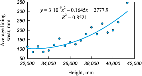
The negative value of the lining wear at the height of +43,900 mm is explained by the shift in the position of the throat armour segments as a result of prolonged operation. The graphical representation of the variations in the lining wear value depending on the height of the blast furnace shaft is shown in Fig. 3.
Fig. 3. Variations in the actual wear of the refractory lining |
Thus, the maximum wear of the refractory lining in the upper uncooled section of the shaft of blast furnace No. 5 during the 2006 – 2024 campaign was observed in the upper rows of refractories, directly beneath the throat armour segments, and amounted to 242–344 mm, or 37.4 % of the original lining thickness. At deeper levels, up to 10 m below the charge level, the lining wear did not exceed 100 – 150 mm, or 11 – 16 % of the original thickness. During the previous campaign of the furnace (1996 – 2006), a significant reduction in the thickness of the shaft lining was recorded – the upper rows had a residual thickness of 270 – 300 mm, and the wear of the uncooled section of the shaft reached 67 %, which was 1.8 times greater than in the current campaign.
The condition of the cooled section of the shaft of blast furnace No. 5 based on the results of the current campaign is shown in Fig. 4. The dashed line (А – В) indicates the boundary of the uncooled section of the shaft, below which is located the combined cooling system consisting of alternating rows of plate and horizontal coolers. The broken line (С – D – E – F … – K) represents the vertically hidden rows of shaft coolers under the lining, with the segments C – D, E – F, etc., corresponding to the space occupied by the rows of plate coolers. From Fig. 4, it can be seen that the lining in the cooled section was preserved up to a height of four to six rows of plate coolers. Intensive wear of the shaft was recorded below the third row from the top of the cooled section of the plate coolers or below the level of +30,500 mm. The wear ranges from 340 mm (according to the design, from the original lining to the nose part of the horizontal cooler of the shaft) to 510 mm (wear based on the results of the 3D scan) in the areas of the plate coolers.
Fig. 4. Condition of the refractory lining in the cooled section of blast furnace shaft No. 5, |
It is worth noting the relatively satisfactory condition of the blast furnace shaft cooling system elements during the current campaign. The top four rows of plate coolers and up to eight upper rows of horizontal coolers remain protected by refractory lining. The coolers located below have largely retained their operability. In total, during the current campaign, 146 plate coolers, 262 horizontal shaft coolers, and 1 bosh cooler were damaged, accounting for 23.2, 45.2, and 0.01 % of the total number of coolers of these types, respectively. In the previous campaign (1995 – 2006), 9 plate coolers, 221 horizontal coolers, and 25 bosh coolers were damaged, or 1.4, 38.1, and 20.8 % of the total number of these coolers, respectively. Pig iron production at blast furnace No. 5 amounted to 75.18 million tons in the current campaign and 39.48 million tons in the previous campaign, while the total number of damaged elements of the cooling system above the tuyeres was 409 and 255 units, respectively. Thus, 183.8 thousand tons of pig iron were produced per damaged cooling element in the bosh and shaft system during the current campaign, which is 19 % higher than the previous campaign’s figure of 154.8 thousand tons of pig iron per damaged element.
A comparison of the results of the previous and current campaigns suggests the high effectiveness of the measures applied to protect the refractory lining and the cooling elements of the bosh and shaft, which included:
– the use of a previously developed method to ensure the self-renewal of the protective skull in the shaft [8], which involves the cyclical loading of charge materials, including a skull-forming mixture consisting of iron ore and sinter. This mixture generates primary slag melt in the amount of 20 – 25 %, with an iron oxide content in this melt of no more than 15 %;
– the development and application of methods during the current campaign for the effective distribution of various types of solid fuel across the furnace’s cross-section, and a material distribution system that includes a predetermined distribution of ore load across the furnace’s cross-section. This also involves the cyclic use of axial, pre-washing, and washing batches to ensure the central operation of the furnace under variable charge and gas-blowing conditions [6].
It is important to note that the study of the condition of the refractory lining in the shaft of blast furnace No. 5 was conducted within very tight time frames. The total scanning time at four stations was 50 min, which allowed the repair work on the furnace to proceed without delay.
Measurement of refractory lining thickness in the tuyere zone and hearth of BF No. 5
The measurement of refractory lining thickness in the hearth and bottom areas was carried out during the raking out of residual charge materials from the working space of blast furnace No. 5. To prevent people from entering the danger zone, a remote measurement method was used, capturing photographic images of refractory lining elements and scaling the linear dimensions of these elements against known dimensions of the furnace structure that remain unchanged during operation (such as the thickness of the shell, plate coolers in the hearth, and bottom, etc.). This method not only allows for safe measurements but also significantly reduces the time required for the study, as the photographic documentation occurs quickly during technological pauses in the raking process, and the mathematical processing of the results can be done at any convenient time. In this study, the procedure for comparing the dimensions of objects by measuring the lengths of lines recorded in the photographs was performed using the digital tool Visio. The known linear dimension used for scaling was the thickness of the hearth cooling stave, which is 160 mm.
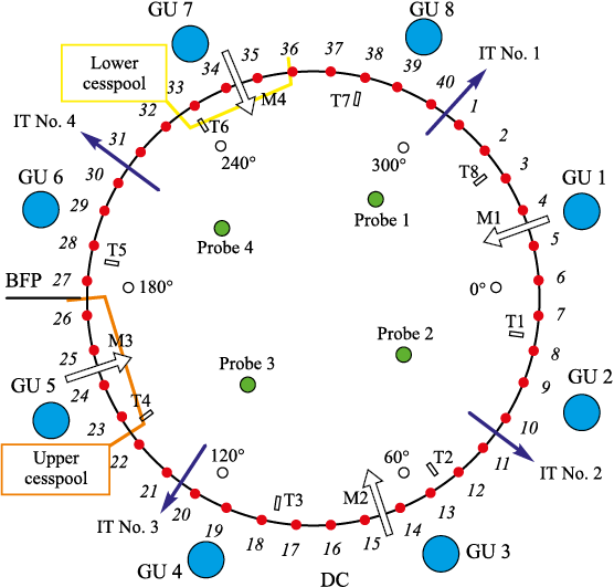
The raking of residual charge materials was performed through two cesspools installed in the furnace shell at the level of the tuyere zone (upper) and bottom (lower). A map showing the location of the cesspools in the horizontal section of the hearth of blast furnace No. 5, with reference to the main structural elements, is presented in Fig. 5.
Fig. 5. Map showing the location of cesspools in the horizontal section of the hearth |
The tuyeres are positioned around the circumference at intervals of 360/40 = 9°. The right side of the lower cesspool, where the residual thickness of the carbon blocks was measured, is located 17.15° to the left of the axis of iron taphole No. 4, corresponding to the area between tuyeres 32 and 33 (9/2 + 9 = 13.5° and 9/2 + 9 + 9 = 22.5°, respectively). The left side of the lower cesspool, where the residual thickness of the carbon blocks was measured, is located 31.7 + 17.15 = 48.85° to the left of the axis of iron taphole No. 4, corresponding to the area of tuyere 36 (9/2 + 9·5 = 49.5°).
The right side of the upper cesspool is located 18.15° to the left of the axis of iron taphole No. 3, which corresponds to the area between tuyeres 22 and 23 (9/2 + 9 = 13.5° and 9/2 + 9 + 9 = 22.5°, respectively). The left side of the upper cesspool is located 35.7 + 18.15 = 53.85° to the left of the axis of iron taphole No. 3, which corresponds to the area between tuyeres 26 and 27 (9/2 + 9ꞏ5 = = 49.5° and 9/2 + 9ꞏ6 = 58.5°, respectively).
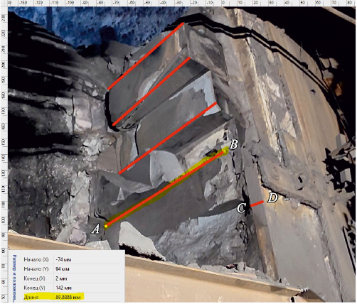
An example of using the Visio tool to measure the residual thickness of carbon refractory blocks in the right side of the lower cesspool (between tuyeres 32 and 33) is shown in Fig. 6. In this example, considering the scale, the actual residual size of the block is calculated as
89.8888ꞏ160/7.4677 = 1926 mm,
where 89.8888 is the size of the block in the photograph, mm, 160 is the design thickness of the cast iron stave, mm, and 7.4677 is the thickness of the cooler in the photograph, mm.
Fig. 6. Example of using the Visio tool to determine the residual linear size |
The results of the calculation of the residual thickness of the carbon block correspond well with the control measurement taken during a technological pause in the raking process. The same method was used to assess the residual thickness of the refractories along the height of both the lower and upper cesspools.
The measurements performed made it possible to create a map of the actual erosion of the carbon blocks in the area of the lower cesspool between tuyeres 32 and 36, which is presented in Table 2.
Table 2. Actual wear of the carbon refractory blocks in the hearth
| |||||||||||||||||||||||||||||||||||||||||
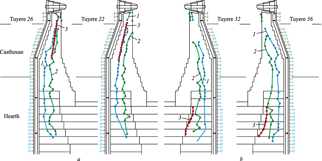
Using the same method as for measuring the actual wear of the carbon blocks in the area of the lower cesspool, the residual thickness of the refractory lining in the hearth was measured near the upper cesspool. This allowed the formation of actual erosion lines of the bottom and hearth lining of blast furnace No. 5 along vertical sections in the areas of tuyeres 22, 26, and 32, 36, respectively. A graphical representation of these lines, compared with the results of ultrasonic echo-sounding (AU-E), is shown in Fig. 7.
Fig. 7. Graphical representation of the actual erosion of the refractory lining in the hearth |
The AU-E method is a technology that uses stress wave propagation and data analysis in both the time and frequency domains to determine lining thickness or detect anomalies, such as cracks, voids, or metal penetration into the lining [9 – 11]. During the measurements, a mechanical impact on the surface of the structure (using a hammer or an impact-mechanical source) generates a stress impulse, which propagates through the lining layers. The wave is partially reflected due to changes in the properties of the lining layer, but the primary wave energy propagates through the continuous layers until it fully dissipates. Compression waves reach the sensors/receivers, and the signals are analyzed to provide a qualitative assessment of the lining. Factors such as density, temperature gradient, geometry, and elasticity properties affect the wave speed. A sudden change in density and/or elasticity properties of the material leads to partial or full wave reflection. Thus, signals are reflected by interfaces, such as the lining-metal melt boundary or the interfaces between refractory blocks. Additionally, stress-free zones, such as cracks and voids, also result in partial or full reflection of the signals. It should be noted that during the AU-E ultrasonic sounding performed by HATCH specialists, several significant reservations were made, specifically:
– the AU-E method can only detect cracks that run parallel to the furnace shell (i.e., perpendicular to the signal direction from the impact). Any cracks or delaminations parallel to the signal direction (i.e., toward the furnace center) cannot be detected;
– “stable lining” refers to unchanged lining that is in almost the same condition as when it was manufactured, whereas “modified lining” has likely undergone significant changes or cracking.
Comparing the actual erosion lines shown in Fig. 7 with the results of ultrasonic echo-sounding (AU-E), the following conclusions can be drawn:
– in the upper part of the hearth, lined with refractory brick containing 43 % Al2O3 , the echo-sounding method shows satisfactory accuracy. Actual measurements of the minimum residual lining thickness range from 220 to 330 mm (excluding skull), which corresponds to the results of the ultrasonic sounding;
– in the lower part of the hearth and the bottom, lined with carbon blocks, the HATCH specialists’ measurements showed extremely low values of residual lining thickness (an average value around the circumference and height of the hearth was 540 mm, or 21 % of the original thickness, with a minimum value of 240 mm, or 10 % of the original thickness). Even considering the reservations and the “modified lining with skull” line presented in the reports, the actual residual thickness of the carbon blocks, measured during the repair, exceeded 80 %, meaning it was significantly higher.
The data in Table 2 and Fig. 7 allow for an assessment of the effectiveness of the measures taken during the current campaign of blast furnace No. 5 to ensure the preservation of the refractory lining in the hearth and bottom. It is known that the factors determining the wear of refractory linings include:
– abrasive action of liquid iron flows;
– chemical impact of iron and slag;
– infiltration and thermomechanical stress in the lining [12 – 14]. It is widely recognized that the service life of the hearth lining is largely determined by the quality of the coke being charged, and that there are currently no wear-resistant hearth designs [15].
In the current campaign, measures were developed and consistently implemented to prevent the development of abrasive action by liquid iron flows in the peripheral (near-wall) zone, ensuring the intensive filtration of molten products through the totterman and good gas permeability in the furnace’s central zone. Under real blast furnace operating conditions, due to fluctuations in the coke’s hot strength (CSR), water entering the hearth from defective elements of the cooling system, and the introduction of localized masses of high-melting-point components in the blast furnace charge, the porosity of the totterman can significantly decrease. Continuous monitoring of the permeability of the furnace’s central zone was organized through totterman probing. To clean the hearth from high-melting-point flux residues and small coke fractions, comprehensive washing of the hearth volume was introduced. To reduce the chemical erosion of the carbon blocks in the hearth and bottom due to the non-equilibrium chemical composition of the molten iron, a method for controlling the technological process was developed by monitoring the ratio of actual carbon content in the iron (Ac ) to the saturation content (Sc ) through the regulation of natural gas injection into the furnace.
Comparing the results of the previous campaign of blast furnace No. 5 (by the end of 2006, the refractory thickness around the iron tapholes did not exceed 200 – 250 mm, and the carbon peripheral blocks in the upper bottom area, located directly below the tapholes, were deformed with cracks and chips in some places) with the data in Table 2, we can conclude that the measures taken during the current campaign significantly improved the durability of the carbon lining in the hearth and bottom.
As a numerical assessment of the effectiveness of the measures to extend the campaign of blast furnace No. 5, the total pig iron production per hearth area in the current campaign reached 420.0 thousand tons/m2, exceeding the previous campaign’s figure of 220.6 thousand tons/m2 by 1.90 times, or by 90.4 %.
At the same time, the results of the studies on the residual thickness of the lining indicate that the tuyere zone requires the development of additional protective measures for the next furnace campaign.
Map of the actual erosion of the refractory lining in BF No. 5
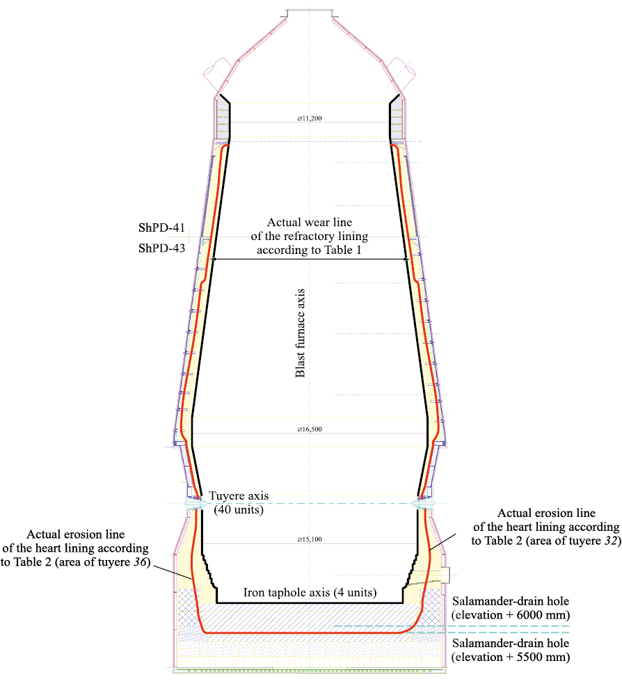
Based on the results of the study of the working space of blast furnace No. 5, a comprehensive map of the actual erosion of the lining during the 2006 – 2024 campaign was created, as shown in Fig. 8.
Fig. 8. Map of the actual erosion of the refractory lining of blast furnace No. 5 |
Conclusions
As a result of comprehensive studies conducted during the first-category overhaul of blast furnace No. 5, the effectiveness of the measures developed and implemented during the current campaign to protect the refractory lining of the shaft, hearth, and metal receiver of the furnace was confirmed. These measures extended the furnace’s service life by 1.75 times and ensured its highly efficient operation throughout the 2006 – 2024 campaign.
Using remote measurement techniques, including 3D laser scanning, the actual erosion profile of the refractory lining of blast furnace No. 5 was determined, and areas of increased erosion with reduced residual thickness along the height of the furnace were identified.
The analysis of the actual residual thickness of the refractory lining in the hearth of blast furnace No. 5 demonstrated satisfactory accuracy of the AU-E ultrasonic sounding method in the area of the alumina refractory lining of the tuyere zone, but insufficient accuracy when measuring the carbon blocks.
References
1. Kurunov I.F., Loginov V.N., Tikhonov D.N. Methods of extending a blast-furnace campaign. Metallurgist. 2006;50: 605–613. https://doi.org/10.1007/s11015-006-0131-5
2. Vinogradov E., Karimov M., Dmitriev A., etc. Blast furnace campaign extension at CherMK, Severstal. In: AISTech 2018 Proceedings – Iron and Steel Technology Conference and Exposition. 2018:551–560.
3. Mozharenko N.M., Kanaev V.V., Panchokha G.V. Influence of smelting technology on metal receiver lining of blast furnace. Metallurgicheskaya i gornorudnaya promyshlennost’. 2003;(5):5–8. (In Russ.).
4. The influence of blast furnace productivity on the duration of its campaign. Novosti chernoi metallurgii za rubezhom. 2005;(1):21–24. (In Russ.).
5. Shul’te M., Klima R., Ringel’ D., Foss M. Monitoring the wear of the blast furnace hearth using heat flow sensors. Chernye metally. 1998;(4):17–22. (In Russ.).
6. Kal’ko A.A., Vinogradov E.N., Kal’ko O.A., Kal’ko A.A. Development and implementation of technological measures to extend the campaign of blast furnace No. 5 of PJSC Severstal. Izvestiya. Ferrous Metallurgy. 2024;67(3): 260–269. https://doi.org/10.17073/0368-0797-2024-3-260-269
7. Medic M.Sc.T. Efficient calibration strategies for panoramic terrestrial laser scanners. Dissertation Zur Erlangung des akademischen Grades Doktor der Ingenieurwissenschaften (Dr.–Ing.). Bonn: Institut für Geodäsie und Geoinformation der Universität Bonn; 2021.
8. Loginov V.N., Sukhanov M.Yu., Gurkin M.A., Vasil’ev L.E., Karimov M.M., Bol’shakov V.I., Nesterov A.S., Mozharenko N.M., Yakushev V.S. Method for creating a protective skull in a blast furnace shaft. Patent RF no. 2251575. МPК С21В 5/00. Byulleten’ izobretenii. 2005;(13). (In Russ.).
9. Gebski P., Sadri A., Ying W. Development of the system for furnace integrity monitoring based on real-time continuous acoustic emission data acquisition and analysis. In: Conf. of Metallurgists (COM), October 2–5, 2011, Montreal, Canada, 2011.
10. Vinogradov E., Kalko A., Chikinov S., Ivashov A., Balahonov D., Gurkin M., Karunova E., Gordon Y., Sadri A., Busser J. Development of strategy for sustaining, enhancement and cost reduction at Severstal’s primary end. In: Proceedings of the Iron & Steel Technology Conference. Association for Iron and Steel Technology; 2020:178–186.
11. Vinogradov E., Karimov M., Dmitriev A. Careful control of refractory lining conditions to ensures prolonged campaign of blast furnace. In: 7th ECIC Proceedings, Linz, Austria, 2016.
12. Kaplun L.I., Malygin A.V., Onorin O.P., Parkhachev A.V. Construction and Design of Blast Furnaces: Tutorial. Ekaterinburg: URFU; 2016:217. (In Russ.).
13. Bliznyukov A.S., Feshchenko S.A., Kurunov I.F., etc. Study of the blast furnace hearth lining. Message 1. Ferrous Metallurgy. Bulletin of Scientific, Technical and Economic Information. 2010;(9):31–36. (In Russ.).
14. Bol’shakov V.I., Gladkov N.A., Murav’eva I.G., etc. The structure of the lower part of the charge column and the role of its elements in the organization of smelting processes. In: Proceedings of IFM. Fundamental and Applied Problems of Ferrous Metallurgy. 2004;(8):112–119. (In Russ.).
15. Koval’ski V., Lyungen Kh.B., Shtrikker K.P. Durability of blast furnaces: Current level, development and company development measures. Chernye metally. 1999;(9):26–35. (In Russ.).
About the Authors
A. A. Kal’koRussian Federation
Andrei A. Kal’ko, Head of Technological Development Center Upstream
30 Mira Str., Cherepovets, Vologda Region 162608, Russian Federation
L. I. Leont’ev
Russian Federation
Leopol’d I. Leont’ev, Academician, Adviser, Russian Academy of Sciences; Advisor to the General Director, I.P. Bardin Central Research Institute of Ferrous Metallurgy
23/9 Radio Str., Moscow 105005, Russian Federation
32a Leninskii Ave., Moscow 119991, Russian Federation
E. A. Volkov
Russian Federation
Evgenii A. Volkov, Leading Expert of Technological Development Center Upstream
30 Mira Str., Cherepovets, Vologda Region 162608, Russian Federation
Review
For citations:
Kal’ko A.A., Leont’ev L.I., Volkov E.A. Assessment of the effectiveness of technological measures to extend the campaign of blast furnace No. 5 of PJSC Severstal (2006 – 2024) based on an examination of its working space during a first-category overhaul. Izvestiya. Ferrous Metallurgy. 2024;67(5):520-530. https://doi.org/10.17073/0368-0797-2024-5-520-530


