Scroll to:
Approaches to the selection of material design of infrastructure facilities for transport and injection of СО2
https://doi.org/10.17073/0368-0797-2024-2-229-236
Abstract
The article is devoted to the study of dependence of carbon dioxide corrosion rate on the microstructure of material design of the pipeline for CO2 transport and injection. Today there is a task of choosing such material design. For pipeline construction the most cost-effective materials are carbon steels, but for their application it is necessary to pay increased attention to the problem of carbon dioxide corrosion, which is intensified in wet, undrained CO2 flows. At the same time, the choice of material should be made reasonably, taking into account the balance between corrosion resistance, mechanical characteristics and economic aspect of the issue. In this paper, the influence of microstructural state features on the corrosion rate of low-alloy mild steels for CO2 transport and injection was investigated. The authors studied the features of steels with ferritic-bainitic, bainitic-ferritic-perlitic and ferritic-perlitic microstructures. Tests on corrosion resistance were carried out on the bench autoclave complex, which allows to recreate conditions of high pressure and temperature and to simulate real environments. It was determined that the microstructural state of steel has a significant effect on the corrosion rate, which increases with increasing volume fraction of pearlite. Understanding the relationship between the microstructural characteristics of steels and corrosion rates can simplify material selection for infrastructure facilities and contribute to more efficient and reliable use of low-alloy carbon steels in carbon capture, use, and storage projects. This study will be useful in selecting favorable microstructures for low-alloy mild steels that can be used for CCUS (Carbon Capture, Use and Storage) infrastructure projects.
Keywords
For citations:
Rovbo A.S., Golubev I.A., Shaposhnikov N.O., Penigin A.V., Fedorov A.S. Approaches to the selection of material design of infrastructure facilities for transport and injection of СО2. Izvestiya. Ferrous Metallurgy. 2024;67(2):229-236. https://doi.org/10.17073/0368-0797-2024-2-229-236
Introduction
Carbon capture, use, and storage (CCUS) is a research area aimed at reducing CO2 emissions and combating climate change. In the CCUS process (Carbon Capture, Use and Storage) [1; 2], CO2 emitted into the atmosphere from various sources such as industrial enterprises, power plants, and motor vehicles is captured and subsequently stored in underground formations [3; 4]. This allows for the isolation of carbon dioxide from the atmosphere and prevents its negative impact on the climate.
Currently, there is a challenge in selecting the material design for infrastructure objects used for CO2 transport and injection under increased environmental and economic risks [5; 6]. The selection of material should strike a balance between effectiveness in preventing intensive carbon dioxide corrosion [7] and the cost of the final solution [8].
A review of open sources on the topic of material selection for CCUS facilities [3; 9] has shown that carbon steels are the most economically advantageous materials for pipeline construction [10]. However, their application necessitates increased attention to the problem of carbon dioxide corrosion [11], which intensifies in wet CO2 flows [12]. Additionally, there is no consensus in the literature regarding the influence of steel microstructure and thermomechanical treatment modes on the mechanism and kinetics of corrosion processes [13 – 16]. This is because conditions can vary from one facility to another in terms of mineralization, component composition of environments, partial pressure, and temperature. Consequently, corrosion product deposits of varying morphology form on the steel surface, which can either be protective or accelerate the corrosion process. Therefore, the selection of materials must consider the operational conditions and actual environments at the facility. In this context, the goal of the present work is to investigate the influence of microstructural state features on the corrosion rate of low-alloy mild steels for CO2 transport and injection, based on the conditions of a specific facility.
Materials and method
To recreate the conditions of actual facilities, various bench setups are used, such as closed-loop flow stands or autoclave setups that replicate conditions of high pressure and temperature. In this work, an autoclave setup with a 3-liter capacity vessel was used. Currently, there are no standard methodologies for conducting corrosion tests in autoclaves, so the methodology used in this experiment is described below. The test conditions were selected based on the situation at the actual facility.
The essence of the corrosion testing method is to determine the mass loss of samples during their exposure to the corrosive environment. In the gravimetric method, the corrosion rate is determined by the mass parameter ρ, expressed in g/m2·h:
| \[\rho = \frac{{{m_1} - {m_2}}}{{S\tau }},\] | (1) |
where m1 is the mass of the sample before testing, g; m2 is the mass of the sample after testing, g; S is the surface area of the sample, m2; τ is the duration of the test, h.
If the change in mass is directly proportional to the depth of corrosion penetration under uniform corrosion conditions, the corrosion rate is recalculated into the depth parameter v, expressed in mm/year. This parameter characterizes the uniform corrosion loss (thinning) of the sample per unit time:
| \[v = \frac{{8760\rho }}{{7.85 \cdot {{10}^3}}},\] | (2) |
where v is the depth parameter of the corrosion rate, mm/year; 8760 is the number of hours in a year; 7.85 is the density of the investigated steel, g/cm3.
The gravimetric method allows for highly accurate results, as weighing is one of the most precise operations in quantitative analysis. The confidence interval for determining measurement error was 95 %.
Before testing, the samples were degreased using an ultrasonic cleaner in acetone, air-dried, and placed on a suspension in the autoclave, which was then sealed and deaerated for 60 min with an inert gas flow rate of 100 ml/min per liter of capacity. The deaerated test solution was then saturated with CO2 . The total pressure in the autoclave was 6 MPa, with a partial pressure of CO2 at 0.3 MPa. The temperature was maintained constant at 25 °C. The test duration was 96 h. For corrosion tests, three samples were selected from each steel.
The test solution consisted of 133 g/l CaCl2 , 31 g/l MgCl2 , 0.5 g/l NaHCO3 , 0.1 g/l Na2SO4 in distilled water. The total mineralization was 164.6 g/l. This composition corresponds to the fluid composition in the well being injected with CO2 into underground formations. After testing, the samples were washed and air-dried, then cleaned of corrosion products using an eraser. The investigated steels correspond to the strength class K52, with their chemical composition presented in Table 1.
Table 1. Chemical compositions of the studied steels
| |||||||||||||||||||||||||||||||||||||||||||||||||||||||||||||||||
The microstructure of the steels was evaluated using a Reichert-Jung MEF3A optical microscope. To perform a quantitative assessment of the phase components, etching was selected to provide a contrasting image of the phases without revealing grain boundaries for subsequent automatic recognition by the Thixomet Pro image analyzer [17]. For this purpose, etching with a 4 % alcoholic solution of picric acid was used to reveal pearlite. For overall microstructure identification, a 3 % nitric acid solution in alcohol was used.
The traditional method for grain size assessment is described in GOST 5639 – 82, which, however, does not allow for the assessment of the heterogeneity of the grain structure. Nowadays, many methods for evaluating the grain structure of a material are known [18; 19]. For instance, in [20], a method for calculating the grain size variation factor FZ is proposed by the formula
| \[{F_Z} = \frac{{{f_{\max }}{Z_{\max }}}}{{\sum {{f_i}{Z_i}} }},\] | (3) |
where fmax is the fraction of the grain occupying the maximum area on the cross-section, %; Zmax is the grade of the grain occupying the maximum area on the cross-section; fi is the fraction of the grain with a specific grade, %; Zi is the grade of the grain.
Results of the quantitative assessment
of structural components and corrosion testing
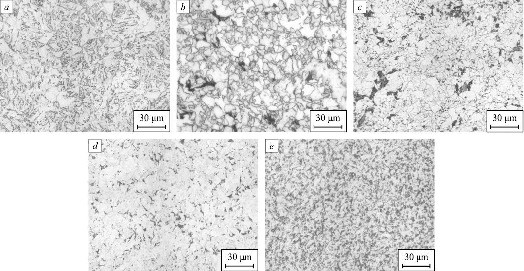
The materials investigated in this study were obtained from various domestic metallurgical enterprises using a technology that includes converter smelting, ladle treatment, continuous casting, followed by thermomechanical processing. The microstructures of the steels were examined in cross-section (Fig. 1).
Fig. 1. General view of microstructures of the studied steels: |
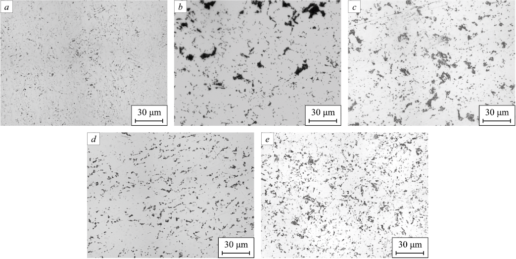
The microstructure of steel 1 is characterized as ferritic-bainitic. The pearlite content in this steel is the lowest among all the steels studied, at 2.20 vol. %, and the grain structure (by the grain number occupying more than 10 % of the cross-section area) is evaluated as G10 (30 %) and G11 (28 %). The microstructure of steel 2 is characterized as ferritic-pearlitic with predominantly non-polygonal ferrite, with the grain structure evaluated as G9 (13 %) and G10 (21 %). The pearlite content in this steel is 3.57 vol. %. The microstructure of steel 3 is also characterized as ferritic-pearlitic. The structure is evaluated as G11 (32 %) and G12 (32 %), and the pearlite content is 6.72 vol. %. The distribution of pearlite colonies is uneven, appearing as separate clusters with coarse morphology, similar to steel 2 (Fig. 2). The microstructure of steel 4 is characterized as ferritic-pearlitic-bainitic, with a pearlite content of 7.51 vol. %. The distribution of pearlite in this steel is fairly uniform, and the structure is evaluated as G9 (14 %), G10 (28 %), G11 (29 %), and G12 (18 %). The microstructure of steel 5 is characterized as ferritic-pearlitic. This steel has the highest pearlite content, 13.80 vol. %, after etching with picric acid. The structure is evaluated as G10 (21 %), G11 (32 %), and G12 (25 %).
Fig. 2. Detection of perlite in the studied steels: |
Results and discussion
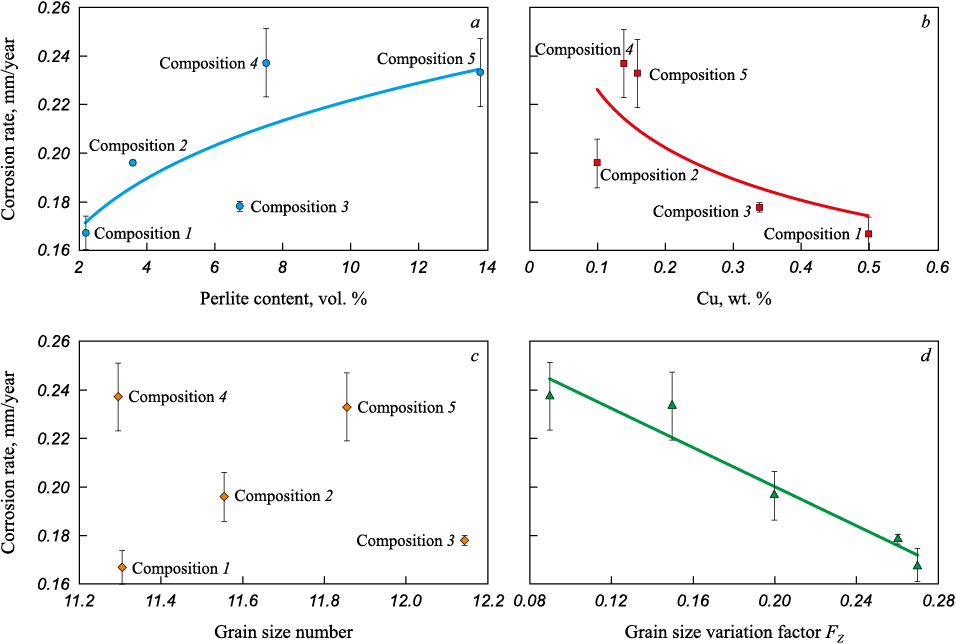
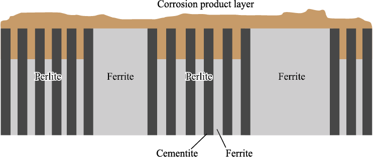
In ferritic-pearlitic steels, pearlite consists of a lamellar structure composed of alternating layers of ferrite and iron carbide (cementite). When exposed to aggressive media containing CO2 , the ferrite in the pearlite becomes the anode and dissolves quickly, while the cementite remains intact (Fig. 4). The carbon content is directly proportional to the pearlite content. The results of the corrosion tests shown in Fig. 3, a demonstrate that as the pearlite fraction in the microstructure increases, the overall corrosion resistance of the steels decreases.
Fig. 3. Dependence of corrosion rate of the studied steels on:
Fig. 4. Mechanism of corrosion of ferritic-perlitic steels in CO2-containing environments [22] |
The study [21] indicates that the most vulnerable areas are the boundaries between ferrite and cementite, where corrosion processes initially begin. It appears that increasing the number of pearlite colony areas leads to an increase in the number of vulnerable ferrite-cementite interphase boundaries and ferrite plates, which subsequently become anodes and dissolve quickly.
It is also worth noting the positive effect of copper on corrosion resistance – increasing the copper content from ~0.12 to 0.50 wt. % led to a reduction in the corrosion rate from 0.237 to 0.167 mm/year (Fig. 3, b). The beneficial effect of copper on the corrosion properties of steels is noted in many studies. For instance, in [23], it was found that the introduction of a small amount of copper (usually up to 1 %) significantly enhances the corrosion resistance of low-carbon steels. Moreover, in high-strength low-alloy steels, copper is an alloying element that provides high toughness and good weldability. However, despite the advantages of adding copper to steel composition and the corrosion characteristics of ferritic-pearlitic microstructures demonstrated in this work, low-alloy mild steels should be used cautiously for the material design of CO2 transport and injection infrastructure objects, and only with strict control over the presence of free water in the transported gas – its amount should be minimal. Otherwise, corrosion-resistant materials must be used.
Based on the evaluation of the microstructural parameters of the investigated steels presented in Table 2, it can be concluded that grain size does not have a determining influence on the corrosion resistance of the investigated steels (Fig. 3, c). However, the grain size variation, assessed by equation (3), significantly affects corrosion resistance (Fig. 3, d). Therefore, it can be concluded that the higher the uniformity of the structure (and, accordingly, the value of the FZ factor), the higher the corrosion resistance of the material.
Table 2. Results of assessment of the steels microstructure parameters
|
Conclusions
A study was conducted on the influence of microstructural state features on the corrosion rate of low-alloy mild steels for CO2 transport and injection (CCUS). It was shown that in ferritic-pearlitic steels, ferrite is primarily susceptible to corrosion processes, becoming an anode and dissolving quickly within pearlite. As a result, increasing the number of pearlite colony areas in the microstructure leads to a decrease in the overall corrosion resistance of the steel. The positive effect of copper on corrosion resistance was established – increasing the copper content in the investigated compositions from 0.12 to 0.50 wt. % led to a 1.5-fold reduction in the corrosion rate. It was noted that corrosion resistance is significantly influenced not by grain size, but primarily by the heterogeneity of the structure.
References
1. Barker R., Hua Y., Neville A. Internal corrosion of carbon steel pipelines for dense-phase CO2 transport in carbon capture and storage (CCS) – a review. International Materials Reviews. 2017;62(1):1–31. https://doi.org/10.1080/09506608.2016.1176306
2. Zhang Y., Pang X., Qu S., Li X., Gao K. Discussion of the CO2 corrosion mechanism between low partial pressure and supercritical condition. Corrosion Science. 2012;59:186–197. https://doi.org/10.1016/j.corsci.2012.03.006
3. Cecile M., Dwaipayan M., Guillaume N., Leila F. Material integrity aspects of CCS: an overview for CO2 transport and storage. In: Trondheim Conference on CO2 Capture, Transport and Storage Trondheim, Norway – June 21–23, 2021: 231–236.
4. IEAGHG. Corrosion and Selection of Materials for Carbon Capture and Storage. 2010; 288.
5. Witkowski A., Majkut M., Rulik S. Analysis of pipeline transportation systems for carbon dioxide sequestration. Archives of Thermodynamics. 2014;35(1):117–140. https://doi.org/10.2478/aoter-2014-0008
6. Witkowski A., Rusin M., Majkut S., Rulik K. Advances in Carbon Dioxide Compression and Pipeline Transportation Processes. Springer Cham; 2015:134. https://doi.org/10.1007/978-3-319-18404-3
7. Wang S., Zhao J., Gu Y., Xiong D., Zeng Q., Tian B. Experimental and numerical investigation into the corrosion performance of X100 pipeline steel under a different flow rate in CO2-saturated produced water. Journal of Solid State Electrochemistry. 2021;25(3):993–1006. https://doi.org/10.1007/s10008-020-04868-9
8. Knoope M.M.J., Guijt W., Ramirez A., Faaij A.P.C. Improved cost models for optimizing CO2 pipeline configuration for point-to-point pipelines and simple networks. International Journal of Greenhouse Gas Control. 2014;22:25–46. https://doi.org/10.1016/j.ijggc.2013.12.016
9. Duong C. Quest carbon capture and storage offset project: Findings and learnings from 1st reporting period. International Journal of Greenhouse Gas Control. 2019;89:65–75. https://doi.org/10.1016/j.ijggc.2019.06.001
10. Wang Z.M., Liu X.T., Han X., Zhang J. Managing internal corrosion of mild steel pipelines in CO2 enhanced oil recovery multiphase flow conditions. Energy Technology. 2015;3(3): 225–233. https://doi.org/doi:10.1002/ente.201402159
11. McGrail B.P., Schaef H.T., Glezakou V.A., Dang L.X., Owen A.T. Water reactivity in the liquid and supercritical CO2 phase: Has half the story been neglected? Energy Procedia. 2009;1(1):3415–3419. https://doi.org/10.1016/j.egypro.2009.02.131
12. Yoon-Seok C., Srdjan N., Young D. Effect of impurities on the corrosion behavior of CO2 transmission pipeline steel in supercritical CO2-water environments. Environmental Science and Technology. 2010;44(23):9233–9238. https://doi.org/10.1021/es102578c
13. Lopez D.A., Perez T., Simison S.N. The influence of microstructure and chemical composition of carbon and low alloy steels in CO2 corrosion. A state-of-the-art appraisal. Materials & Design. 2003;24(8):561–575. https://doi.org/10.1016/S0261-3069(03)00158-4
14. Paolinelli L.D., Perez T., Simison S.N. The influence of steel microstructure, chemical composition and precorrosion on CO2 corrosion inhibitor efficiency. In: NACE CORROSION’2007. Houston, U.S.A., March 2007:07311.
15. Xu L.N. Influence of microstructure on mechanical properties and corrosion behavior of 3% Cr steel in CO2 environment. Materials and Corrosion. 2012;63(11):997–1003. https://doi.org/10.1002/maco.201106389
16. Ochoa N., Vega C., Pebere N., Lacaze J., Brito J.L. CO2 corrosion resistance of carbon steel in relation with microstructure changes. Materials Chemistry and Physics. 2015;156:198–205. https://doi.org/10.1016/j.matchemphys.2015.02.047
17. Kazakov A., Kiselev D. Industrial application of thixomet image analyzer for quantitative description of steel and alloy’s microstructure. Metallography, Microstructure and Analysis. 2016;5:294–301. https://doi.org/10.1007/s13632-016-0289-6
18. Grokhovskii V.I. Possibilities of digital microscopy in metallography. In: Digital microscopy. School-seminar materials. Yekaterinburg: USTU-UPI; 2001;(1):18–20. (In Russ.).
19. Lezinskaya E.Ya. Evaluation methods for structure non uniformity of metal for cladding tubes and wrapper of corrosion-resistant steels and alloys. Voprosy atomnoi nauki i tekhniki. Seriya: Fizika radiatsionnykh povrezhdenii i radiatsionnoe materialovedenie = Problems of Atomic Science and Technology. Physics of Radiation Effects and Radiation Materials Science. 2003;(3):108–112. (In Russ.).
20. Lezinskaya E.Ya., Klyuev D.Yu., Nikolaenko Yu.N. New method for assessing the inequigranular structure of pipes of stainless steels and alloys. Teoriya i praktika metallurgii = Theory and Practice of Metallurgy. 2012;(1-2):68–73. (In Russ.).
21. Murase Y., Masuda H., Katayama H. Corrosion resistance of finer/coarser pearlitic structures of carbon steel. Journal of the Electrochemical Society. 2021;168(4):041501. https://doi.org/10.1149/1945-7111/abf185
22. Akeer E.S. Effect of Carbon Steel Composition and Microstructure on CO2 Corrosion. Diss. on degree of Dr.(Ph.). Ohio University; 2014:188.
23. Copper in Ferrous Metals: Coll. of Papers. Mei I. Le, Shetki L.M.-D. eds., Moscow: Metallurgiya; 1988:310. (In Russ.).
About the Authors
A. S. RovboRussian Federation
Anna S. Rovbo, Engineer
29 Politekhnicheskaya Str., St. Petersburg 195251, Russian Federation
I. A. Golubev
Russian Federation
Ivan A. Golubev, Cand. Sci. (Eng.), Research Engineer
29 Politekhnicheskaya Str., St. Petersburg 195251, Russian Federation
N. O. Shaposhnikov
Russian Federation
Nikita O. Shaposhnikov, Cand. Sci. (Eng.), Director of the Scientific and Educational Center “Gazpromneft-Polytech”
29 Politekhnicheskaya Str., St. Petersburg 195251, Russian Federation
A. V. Penigin
Russian Federation
Artem V. Penigin, Project Manager
75–79 D Moika Quay, St. Petersburg 190000, Russian Federation
A. S. Fedorov
Russian Federation
Aleksandr S. Fedorov, Research Engineer of the Scientific and Technological Complex “New Technologies and Materials”
29 Politekhnicheskaya Str., St. Petersburg 195251, Russian Federation
Review
For citations:
Rovbo A.S., Golubev I.A., Shaposhnikov N.O., Penigin A.V., Fedorov A.S. Approaches to the selection of material design of infrastructure facilities for transport and injection of СО2. Izvestiya. Ferrous Metallurgy. 2024;67(2):229-236. https://doi.org/10.17073/0368-0797-2024-2-229-236


