Scroll to:
Mathematical modeling of gas dynamics and off-gas post-combustion above the melt in a melter-gasifier furnace
https://doi.org/10.17073/0368-0797-2024-1-112-120
Abstract
Organization of technological process and design of a furnace significantly affect the parameters of post-combustion, determining the need to develop a mathematical model of post-combustion zone. Modeling of gas dynamics, chemical reactions, convective diffusion and heat transfer in the gas phase above the melt was carried out in an experimental melter-gasifier furnace at three different values of mass flow rates and two positions of post-combustion tuyeres. Temperature distributions and off-gas components concentrations were obtained. It was found that at the lower position of the tuyere, post-combustion is carried out in the area of reflected jet, stagnant zones are formed around the tuyere and between the reflected jet and the melt surface, which decrease the post-combustion level. At the upper position of the tuyere, post-combustion occurs inside the primary jet, intensive mixing of all components of the furnace atmosphere occurs, post-combustion undergoes more completely, which leads to an increase in the off-gases temperature with an increase in uniformity of temperature fields and concentrations compared with the lower position of the tuyere. At the lower position of the tuyere, the flame zone turns out to be open, its shape significantly depends on the mass flow, and the flame zone volume increases with an increase in the mass flow. At the upper position of the tuyere, the flame zone is closed, with an increase in the mass flow, its shape does not change, but the flame zone volume decreases. For reduction processes in slag melt, the upper position of the tuyere is preferable, while for production of the producer gas at the furnace outlet, position of the tuyere closer to the melt surface is preferable.
Keywords
For citations:
Erokhov T.V., Levitskii I.A., Podgorodetskii G.S., Gorbunov V.B. Mathematical modeling of gas dynamics and off-gas post-combustion above the melt in a melter-gasifier furnace. Izvestiya. Ferrous Metallurgy. 2024;67(1):112-120. https://doi.org/10.17073/0368-0797-2024-1-112-120
Introduction
High-temperature bath type smelting reduction furnaces stand out as the most promising technologies for extracting metals from low-grade raw materials (such as refractory ores and iron-containing waste) and for the gasification of coal, including varieties of low-grade coal. The thermal balance for the processes of metal reduction and/or gasification of low-grade coals occurring within the slag melt is achieved by reintroducing heat to the slag bath from the post-combustion of CO and Н2 over the slag. These gases, in turn, results from a series of reduction-oxidation processes taking place within the slag layer [1 – 3].
Mathematical modeling plays a crucial role in understanding the processes occurring during the post-combustion of gases in metallurgical furnaces. For example, studies [4 – 7] delve into modeling the post-combustion process in the electric arc furnace. Post-combustion models for the oxygen converter are outlined in [8], while modifications involving bottom blowing with inert gas, such as the AOD converter and KOBM converter, are discussed in [9 – 11]. Additionally, a significant number of research efforts focus on the modeling of post-combustion in direct iron reduction reactors [12 – 15]. These studies highlight how the specific organization of processes and the design of the furnace greatly influence post-combustion parameters, thereby underscoring the importance of developing mathematical models for the post-combustion zone (the furnace area above the melt) in various furnaces, including the Romelt furnace, Vanyukov furnace, and other bath type smelting reduction furnaces with designated off-gas post-combustion zone.
The aim of this research is to model the gas dynamics, chemical reactions, convective diffusion, and heat transfer in the gas phase above the melt within an experimental melter-gasifier furnace, considering three different blast flow rates and two post-combustion tuyere positions. Mathematical modeling was conducted using Ansys Fluent software, version 15.0.7.
Problem formulation
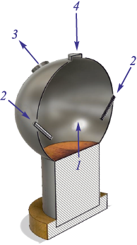
The geometry of the working space within the experimental melter-gasifier furnace is schematically presented in Fig. 1.
Fig. 1. Layout of the experimental melter-gasifier furnace: |
In its standard operational mode, the cylindrical part 1 of the furnace is filled with slag melt. The surface level of this slag melt aligns with the transition between the cylindrical and spherical sections of the furnace. The ongoing chemical reactions within the melt are driven by oxygen-air blastfrom the lower tuyeres (not depicted in the diagram or explored in this study). These processes generate high-temperature gases that rise into the space above the slag, where they fully combust with oxygen-rich air supplied through two upper tuyeres 2. These tuyeres enter the furnace at the center level of the spherical part, angled at 45°.
The flue gases are then emitted through two gas offtakes 3. The gas offtakes axes plane is perpendicular to the upper tuyeres’ axes plane.
The primary geometric dimensions of the furnace (m) are detailed as follows:
Diameter of the spherical part of the furnace 3.00
Diameter of the cylindrical part of the furnace 1.80
Inner diameter of the gas offtake 0.50
Inner diameter of inlet bulk supply window 0.40
Internal diameter of the upper tuyere 0.02
External diameter of the upper tuyere 0.10
Key assumptions
To simplify the calculations, the heat transfer through solid walls (including both the furnace itself and the tuyeres) was not considered. This approach allowed us to exclude the regions occupied by solid materials (the walls of the furnace and tuyeres) from detailed analysis, with the thermal boundary conditions merely acknowledging their existence.
Given that the paper examines the processes in the space above the slag of the furnace, the computational domain was limited to the gas-filled area of the working space – specifically, a sphere with a truncated segment at the bottom and three adjoining small cylindrical elements at the top. This domain includes three inlet cross-sections (the surface of the melt and the inlet cross-sections of the post-combustion tuyeres) and two outlet sections (the openings of the gas offtakes, assuming the bulk supply window is sealed with a lid).
Given that the geometry in question features two planes of symmetry and lacks any elements that would cause swirling in the flows, the modeled value fields exhibit the same symmetry. Consequently, it is sufficient to consider only a quarter of the working space, bounded by the planes of symmetry, as the computational domain for analysis.
In this computational domain, the areas of the inlet and outlet cross-sections are 4 times smaller. Consequently, the flow rates at the inlet sections must be proportionally reduced to reflect their scaled-down size compared to their actual counterparts.
The computational domain’s geometry was outlined using Design Modeler, while the computational mesh was developed and the sections for applying boundary conditions were chosen in Ansys Meshing. The mesh was later converted to a polyhedral format within the Fluent application. This conversion improved the orthogonality of the cell faces and minimized errors associated with so-called schematic diffusion.
For the analysis, we employed several models, including:
– a convection-diffusion heat transfer model which involves solving the energy equation;
– a k-ε turbulence model, specifically the Realizable variant with standard wall functions;
– a component transfer model, that solves the convective diffusion equation and incorporates chemical reactions occurring within the volume. The interaction between kinetics and turbulence adheres to the Finite-Rate/Eddy-Dissipation model.
This last model, which balances the impact of chemical kinetics and turbulent transfer to identify the limiting factor in the process, was utilized in studies [16 – 19] to explore the combustion of methane introduced through a blast furnace tuyere.
Within the framework of this model, the convective diffusion equation for each constituent of the mixture within the computational domain is resolved with reference to its local mass fraction Yi at every computational mesh node. The equation is as follows:
| \[\frac{\partial }{{\partial t}}\left( {{\rm{\rho }}{Y_i}} \right) + \vec \nabla \left( {{\rm{\rho \vec \omega }}{Y_i}} \right) = - \vec \nabla {\vec J_i} + {R_i},\] | (1) |
where ρ is the density of the mixture, kg/m3; \({\rm{\vec \omega }}\) is the velocity vector, m/s; Ri is the rate of formation of the i\(^\rm{th}\) component as a result of chemical reactions, kg/(m3·s); \({\vec J_i}\) is the diffusion flow density of the i\(^\rm{th}\) component, kg/(m2·s). The latter is influenced by the concentration gradients of this component and temperature, which can be expressed as:
| \[{\vec J_i} = - \left( {{\rm{\rho }}{D_{i,m}} + \frac{{{{\rm{\mu }}_t}}}{{S{c_t}}}} \right)\vec \nabla {Y_i} - {D_{T,i}}\frac{{\vec \nabla T}}{T},\] | (2) |
where Di, m and DT, i are the mass diffusion and thermodiffusion coefficients (also known as Soret coefficients) for the component i\(^\rm{th}\), m2/s, respectively; Sct is the turbulent Schmidt number, typically defaulted to 0.7 (\(S{c_t} = \frac{{{{\rm{\mu }}_t}}}{{{\rm{\rho }}{D_t}}},\) where μt is the dynamic coefficient of turbulent viscosity, Pa·s; Dt is the turbulent diffusion coefficient, m2/s).
For a component that is involved in multiple reactions Ri is the sum of the rates of formation of that component from all the reactions \({\hat R_{i,j}}\).
Assuming the reactions are irreversible for simplicity, the j\(^\rm{th}\) reaction can be summarized as:
| \[\sum\limits_{i = 1}^N {{{\nu '}_{i,j}}} {{\rm M}_i}\sum\limits_{i = 1}^N {{{\nu ''}_{i,j}}} {{\rm M}_i},\] | (3) |
where N is the number of chemical components in the system; \({\nu '_{i,j}}\) is the stoichiometric coefficient for the i\(^\rm{th}\) reactant in the j\(^\rm{th}\) reaction; \({\nu ''_{i,j}}\) is the stoichiometric coefficient for the i\(^\rm{th}\) product in the j\(^\rm{th}\) reaction; Mi symbolized the i\(^\rm{th}\) component; kf, i is the rate constant for the forward j\(^\rm{th}\) reaction.
For irreversible reactions, the molar rate of formation/destruction of the i\(^\rm{th}\) component in the j\(^\rm{th}\) reaction is described by the expression:
| \[{\hat R_{i,j}} = ({{\rm{\nu ''}}_{i,j}} - {{\rm{\nu '}}_{i,j}})\left( {{k_{f,j}}\prod\limits_{l = 1}^N {{{\left[ {{C_{l,j}}} \right]}^{({{{\rm{\eta '}}}_{l,j}} + {{{\rm{\eta ''}}}_{l,j}})}}} } \right),\] | (4) |
where Cl, j is the molar concentration of the l\(^\rm{th}\) component in the j\(^\rm{th}\) reaction, kmol/m3; \({\eta '_{l,j}}\) is the reaction rate index of the l\(^\rm{th}\) component in the j\(^\rm{th}\) reaction; \({\eta ''_{l,j}}\) is the reaction rate index of the l\(^\rm{th}\) product in the j\(^\rm{th}\) reaction.
The rate constant for the forward jth reaction is computed using the Arrhenius equation:
| \[{k_{f,j}} = {A_j}{T^{{{\rm{\beta }}_j}}}{e^{ - \frac{{{E_j}}}{{RT}}}},\] | (5) |
where Aj is the pre-exponential indicator (units vary based on the reaction order); βj is the temperature exponent (dimensionless number); Ej is the activation energy for the reaction (J/kmol); R = 8.31 is the universal gas constant (J/(kmol·K)).
This study considered just two combustion reactions, involving hydrogen and carbon monoxide; the equations for these reactions, along with their parameters – some of which were derived from the Ansys Fluent database – are detailed in Table 1.
Table 1. Kinetic constants for the studied chemical reactions [20]
|
At the oxygen-air blast and off-gas inlet cross-sections, parameters such as temperature, mass flow rate, and inlet turbulence characteristics (which include hydraulic diameter and the level of turbulent pulsations) were defined. For the outlet cross-section, parameters set included rarefaction and the temperature and the turbulence characteristics of the external environment immediately adjacent to the outlet (Table 2).
Table 2. Boundary conditions in the calculation
|
The computational task was performed in two stages. Initially, the SIMPLE algorithm was used to solve the gas dynamics equations, with first-order schemes being used for the other equations. Subsequently, the simulation progressed to using a coupled solver for pressure and momentum and second-order schemes for other variables.
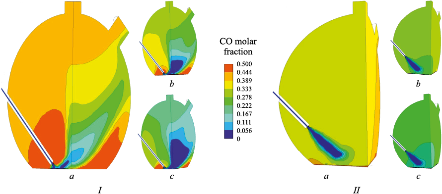
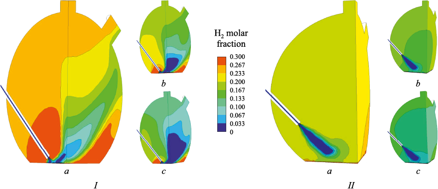
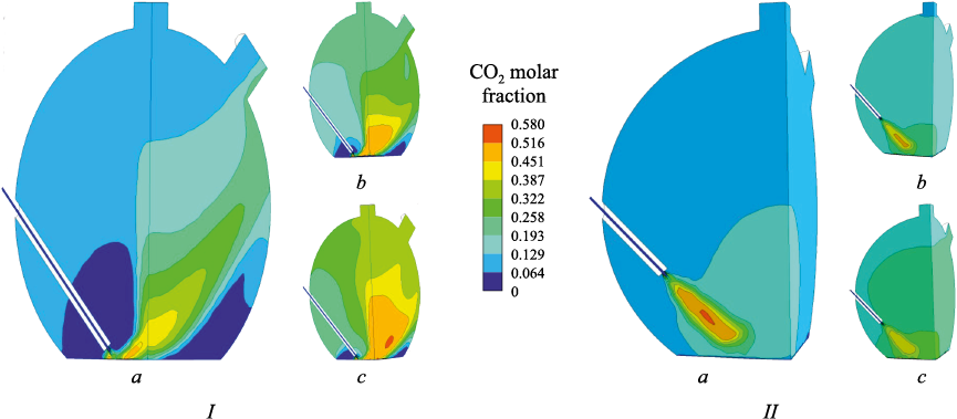
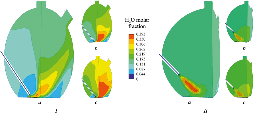
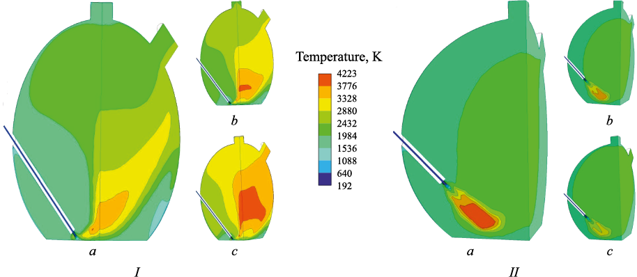
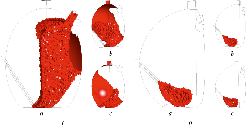
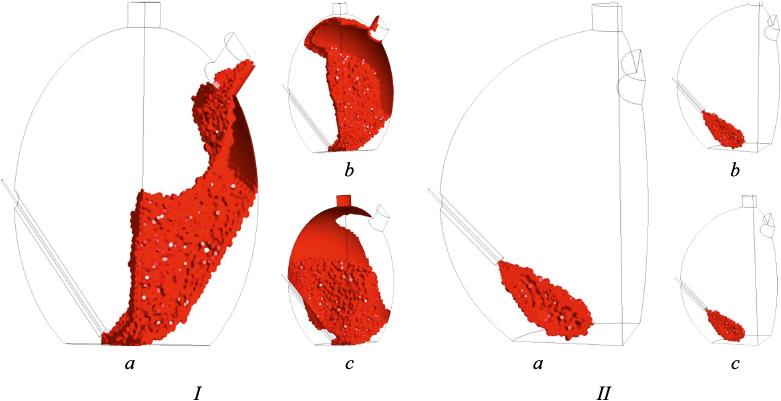
The calculation results shown in Fig. 2 – 5 correspond to three blast flow rates \(\dot M\)b: 0.03919 kg/s (а), 0.07838 kg/s (b), 0.11757 kg/s (c) – these figures should be quadrupled to reflect true values for the full-scale model – and two tuyere positions relative to the melt surface: the lower position I, at 0.1 m from the melt surface, and the upper position II, at 0.7 m from the melt surface.
Fig. 2. Field of CO molar fraction for two variants of the tuyere position (I, II)
Fig. 3. Field of H2 molar fraction for two variants of the tuyere position (I, II)
Fig. 4. Field of CO2 molar fraction for two variants of the tuyere position (I, II)
Fig. 5. Field of H2O molar fraction for two variants of the tuyere position (I, II) |
Fig. 2 – 5 illustrate that increasing the blast flow rate leads to a decrease in the concentrations of post-combustion components (CO and H2 ) and a corresponding increase in the concentrations of combustion products (CO2 and H2O). Moreover, the tuyere’s position significantly impacts both the distribution of these components and the peak values of their concentrations.
With the tuyere positioned at the lower level, the only effective blast jet is the one “reflected” off the melt surface, where the highest concentrations of off-gases are found. These maximum concentrations of off-gases are located in the region near the tuyere above the nozzle and in the area farthest from the nozzle adjacent to the melt surface, influenced by the “reflected” jet.
With the tuyere elevated, the blast mixes more thoroughly with the surrounding components in the space above the slag, leading to most mixing and post-combustion processes happening before the jet reaches the melt surface. In this scenario, the zone of maximum off-gases concentrations forms within the primary blast jet and spreads toward the melt surface. The extreme concentrations are less marked compared to the lower tuyere position, owing to enhanced mixing and the lack of stagnant zones. Consequently, with the tuyere in its upper position, more complete post-combustion is attained, evidenced by the off-gases’ composition at the furnace outlet and the temperature field, which aligns with the concentration field of the combustion products (Fig. 6). This suggests that for producing gas rich in combustible components, positioning the tuyere at a lower level is preferable, whereas for more efficient reduction, a higher tuyere position is advantageous.
Fig. 6. Temperature field for two variants of the tuyere position (I, II) |
Fig. 6 demonstrates that increasing the blast flow rate causes the high-temperature region to expand with the tuyere lowered, but to contract with the tuyere raised.
Ansys Fluent’s Isovolume visualization tool facilitates the creation of three-dimensional surfaces corresponding to specific values of a given quantity, calculated as part of the problem-solving process. Selecting temperature allows for the visualization of concepts such as the flare zone, with Figs. 7 and 8 showcasing isovolumes for temperatures of 2200 and 2600 K, respectively.
Fig. 7. Isovolumes for 2200 K with two variants of the tuyere position (I, II)
Fig. 8. Isovolumes for 2600 K with two variants of the tuyere position (I, II) |
The findings indicate that with the tuyere in the upper position, the flame remains closed, its shape stays consistent with increased blast flow rates, and the volume enclosed by the isosurface decreases. In contrast, raising the blast flow rate significantly alters the configuration of the jet region “reflected” off the melt surface for the lower tuyere, increasing the volume enclosed by the isosurface and causing considerable scattering of the “reflected” jet. This results in an excessive heat flow to the water cooled panels, which is detrimental to the technological process.
Conclusions
Using Ansys Fluent 15.0.7 software, we numerically analyzed the post-combustion of off-gases (CO, H2 ) released from the slag bath’s surface in the experimental melter-gasifier furnace. Our study examined how the oxygen-enriched blast flow rate and the tuyeres’ positioning affect the post-combustion process, including the off-gases’ composition and temperature, flame configuration, and the distribution of temperature and component concentrations within the furnace atmosphere.
We discovered that with the tuyere positioned at the lower level (0.1 m from the nozzle to the melt), post-combustion primarily occurs in the “reflected” jet area. This creates stagnant zones around the tuyere and between the reflected jet and the melt surface, reducing the effectiveness of post-combustion. With the tuyere at the upper level (0.7 m from the nozzle to the melt), post-combustion happens inside the primary jet, leading to intense mixing of all furnace atmosphere components. This results in more complete post-combustion, increasing the off-gas temperature and improving the uniformity of temperature fields and concentrations compared to when the tuyere is at a lower position.
At the lower tuyere position, the flame zone is open, significantly influenced by the mass flow, and its volume increases with the mass flow. With the tuyere in the upper position, the flame zone remains closed, and while its shape stays constant with increased mass flow, the volume of the flame zone decreases.
For reduction processes in the slag melt, higher position of the tuyere is preferable. However, for generating producer gas rich in combustible components at the furnace outlet, a location closer to the melt surface is more advantageous, though it poses a risk of overheating some water cooled panels, potentially harming the furnace structure and affecting other process parameters adversely.
References
1. Romenets V.A., Valavin V.S., Usachev A.B., Karabasov Yu.S., etc. Romelt Process. Moscow: MISIS; 2005:400.
2. Balasanov A.V., Lekherzak V.E., Romenets V.A., Usachev A.B. Coal Gasification in Slag Melt. Moscow: Institut Stal’proekt; 2008:288.
3. Podgorodetskii G.S., Gorbunov V.B., Agapov E.А., Erokhov T.V., Kozlova O.N. Challenges and opportunities of utilization of ash and slag waste of TPP (Thermal Power Plant). Part 2. Izvestiya. Ferrous Metallurgy. 2018;61(7):557–563. (In Russ.). https://doi.org/10.17073/0368-0797-2018-7-557-563
4. Li Y., Fruehan R.J. Computational fluid-dynamics simulation of postcombustion in the electric-arc furnace. Metallurgical and Materials Transactions B. 2003;34(3):333–343. https://doi.org/10.1007/s11663-003-0079-9
5. Arzpeyma N., Ersson M., Jönsson P.G. Mathematical modeling of postcombustion in an electric arc furnace (EAF). Metals. 2019;9(5):547. https://doi.org/10.3390/met9050547
6. Gruber J.C., Echterhof T., Pfeifer H. Investigation on the influence of the arc region on heat and mass transport in an EAF freeboard using numerical modeling. Steel Research International. 2016;87(1):15–28. https://doi.org/10.1002/srin.201400513
7. Tang X., Kirschen M., Abel M., Pfeifer H. Modelling of EAF off-gas post combustion in dedusting systems using CFD methods. Steel Research International. 2003;74(4):201–210. https://doi.org/10.1002/srin.200300182
8. Doh Y., Chapelle P., Jardy A., etc. Toward a full simulation of the basic oxygen furnace: Deformation of the bath free surface and coupled transfer processes associated with the post-combustion in the gas region. Metallurgical and Materials Transactions B. 2013;44(3):653–670. https://doi.org/10.1007/s11663-013-9817-9
9. Tang Y., Fabritius T., Härkki J. Mathematical modeling of the argon oxygen decarburization converter exhaust gas system at the reduction stage. Applied Mathematical Modelling. 2005;29(5):497–514. https://doi.org/10.1016/j.apm.2004.09.011
10. Song Z., Ersson M., Jönsson P. A study of post-combustion in an AOD flue. Steel Research International. 2014;85(7): 1173–1184. https://doi.org/10.1002/srin.201300307
11. Gou H., Irons G.A., Lu W.K. Mathematical modeling of postcombustion in a KOBM converter. Metallurgical and Materials Transactions B. 1993;24(1):179–188. https://doi.org/10.1007/BF02657884
12. Panjkovic V., Truelove J., Ostrovski O. Analysis of performance of an iron-bath reactor using computational fluid dynamics. Applied Mathematical Modelling. 2002;26(2): 203–221.https://doi.org/10.1016/S0307-904X(01)00056-7
13. Shin M.K., Lee S.D., Joo S.H., Yoon J.K. A numerical study on the combustion phenomena occurring at the post combustion stage in bath-type smelting reduction furnace. ISIJ International. 1993;33(3):369–375. https://doi.org/10.2355/isijinternational.33.369
14. Becker-Lemgau U., Tacke K.-H. Mathematical model for post combustion in smelting reduction. Steel Research. 1996;67(4):27–137. https://doi.org/10.1002/srin.199605469
15. Shinotake A., Takamoto Y. Combustion and heat transfer mechanism in iron bath smelting reduction furnace. Metallurgical Research & Technology. 1993;90(7–8):965–974. https://doi.org/10.1051/metal/199390070965
16. Levitskii I.A., Radyuk A.G., Titlyanov A.E., Sidorova T.Yu. Influence of the method of natural gas supplying on gas dynamics and heat transfer in air tuyere of blast furnace. Izvestiya. Ferrous Metallurgy. 2018;61(5):357–363. (In Russ.). https://doi.org/10.17073/0368-0797-2018-5-357-363
17. Gorbatyuk S.M., Tarasov Yu.S., Levitskii I.A., Radyuk A.G., Titlyanov A.E. Effect of a ceramic insert with swirler on gas dynamics and heat exchange in a blast furnace tuyere. Izvestiya. Ferrous Metallurgy. 2019;62(5):337–344. (In Russ.). https://doi.org/10.17073/0368-0797-2019-5-337-344
18. Albul S.V., Kobelev O.A., Radyuk A.G., Titlyanov A.E., Levitskii I.A. Effect of natural gas flow rate and temperature on the processes occurring in a blast furnace tuyere with heat-insulating insert in blast channel. Izvestiya. Ferrous Metallurgy. 2022;65(11):778–785. (In Russ.). https://doi.org/10.17073/0368-0797-2022-11-778-785
19. Radyuk A.G., Gorbatyuk S.M., Tarasov Yu.S., Titlyanov A.E., Aleksakhin A.V. Improvements to mixing of natural gas and hot-air blast in the air tuyeres of blast furnaces with thermal insulation of the blast duct. Metallurgist. 2019;63(5–6):433–440. https://doi.org/10.1007/s11015-019-00843-6
20. Milewski J., Swirski K., Santarelli M., Leone P. Advanced Methods of Solid Oxide Fuel Cell Modeling. London, UK: Springer; 2011:201. https://doi.org/10.1007/978-0-85729-262-9
About the Authors
T. V. ErokhovRussian Federation
4 Leninskii Ave., Moscow 119049, Russian Federation
I. A. Levitskii
Russian Federation
4 Leninskii Ave., Moscow 119049, Russian Federation
G. S. Podgorodetskii
Russian Federation
Gennadii S. Podgorodetskii, Cand. Sci. (Eng.)
4 Leninskii Ave., Moscow 119049, Russian Federation
V. B. Gorbunov
Russian Federation
Vladislav B. Gorbunov, Cand. Sci. (Eng.), Deputy Director of the Research Center “Innovative Metallurgical Technologies”
4 Leninskii Ave., Moscow 119049, Russian Federation
Review
For citations:
Erokhov T.V., Levitskii I.A., Podgorodetskii G.S., Gorbunov V.B. Mathematical modeling of gas dynamics and off-gas post-combustion above the melt in a melter-gasifier furnace. Izvestiya. Ferrous Metallurgy. 2024;67(1):112-120. https://doi.org/10.17073/0368-0797-2024-1-112-120


