Scroll to:
Stress state of billet – mandrel system during production of hollow steel billet in a unit for continuous casting and deformation. Part 1
https://doi.org/10.17073/0368-0797-2023-4-485-491
Abstract
The substantiation of the relevance of obtaining continuous cast steel pipe hollow billet is given from the position of improving the quality of pipes made of carbon and alloy steels is given. The article presents an assessment of the quality of the inner surface of pipes made of solid steel pipe billet. A new technology is proposed for the production of hollow steel pipe billets on a resource-saving unit of combined continuous casting and deformation. The photo of the continuous casting and deformation section of JSC Ural Pipe Plant is given, where a pilot unit of combined continuous casting and deformation is installed. The paper presents the results of a theoretical study of stress-strain state of the mandrel and sections of a pipe billet when it is compressed by the strikers of the unit of combined continuous casting and deformation. The authors discuss the general model of the mold – striker system. The initial data on calculation, dimensions of the hollow pipe billet and a description of the calibration of strikers for compression of a hollow steel billet are given. The temperature field of a hollow billet was determined. To simulate the stress-strain state of the metal in the roll pass and the mandrel, four contact pairs were considered. Calculations were made by the finite element method. The dimensions of the final element in the roll pass of hollow billet were determined. The authors established the values and patterns of changes in metal displacements and axial stresses in the roll pass during the production of hollow steel billets in the unit of combined continuous casting and deformation (strikers are made along a constant radius). The stress state of metal in the roll pass was assessed from the standpoint of improving the quality of hollow steel billets.
For citations:
Lekhov O.S., Mikhalev A.V., Nepryakhin S.O. Stress state of billet – mandrel system during production of hollow steel billet in a unit for continuous casting and deformation. Part 1. Izvestiya. Ferrous Metallurgy. 2023;66(4):485-491. https://doi.org/10.17073/0368-0797-2023-4-485-491
Introduction
In light of the increased output, expansion of the seamless pipes range, and the strengthening of quality requirements, there is a pressing need for research related to the development of new methods and units for producing continuous cast steel pipe hollow billets from carbon and alloy steels. It has been discovered that the quality of the inner surface of pipes produced from hollow billets is superior compared to pipes rolled from solid billets. This is due to the fact that segregation and shrinkage porosity are located within the wall of continuous cast hollow billets, whereas they are concentrated in the core zone of solid billet.
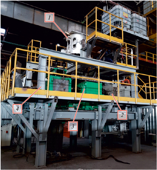
A new technology has been developed for the industrial production of steel pipe hollow billets using a unit for combined continuous casting and deformation (Fig. 1) [1 – 3].
Fig. 1. Unit of continuous casting and deformation: |
The proposed technology involves the formation of a steel annular shell with a wall that contains the liquid phase in a single-piece copper mold. This is followed by the compressing of the wall crusts using strikers, resulting in the displacement of the liquid phase. Afterward, the hardened shell wall is compressed around its entire circumference in a single pass, and the finished hollow billet is calibrated.
Research materials and method
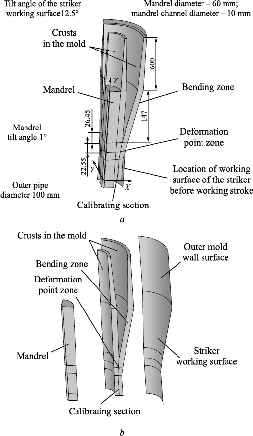
A theoretical study was undertaken to evaluate the new technology for producing hollow steel billets and to establish the fundamental parameters of the unit. A general model of the mold, striker, mandrel, and wall crusts of a hollow billet is depicted in Fig. 2. Dimensions of the deformation areas during bending and compressing of the hollow billet walls by the strikers, the calibration section, and the mandrel are provided. In order to achieve this, it is essential to determine the stress-strain state (SSS) of the metal in the deformation zones during bending and compressing of the hollow billet wall, as well as when subjecting the mandrel to stress during production of a steel hollow billet in the unit.
Fig. 2. Geometry of the mandrel, crusts in the mold, bending zone, roll pass, and striker: |
The elastoplastic contact problem, taking into account significant displacements and deformations, was solved to compute the SSS [4 – 6].
The calculations were performed using the finite element method within the versatile ANSYS 15.0 software package [7 – 9]. Fig. 2 provides a comprehensive overview of the components of the unit of combined continuous casting and deformation, which forms the basis of the calculation model. The key dimensions are as follows: outer pipe diameter – 100 mm, mandrel diameter – 60 mm, internal mandrel channel – 10 mm, calibrating section length – 60 mm, deformation zone – 49 mm, crust thickness in the bending zone – 15 mm, and a 30 mm liquid phase situated between the crusts where ferrostatic pressure has an impact. The tilt angle of the striker working surface is 12.5°, and the mandrel tilt is 1°. The temperature of the inner surface of the pipe billet shell, specifically on the side subjected to ferrostatic pressure, is 1450 °C, while the temperature of the outer surfaces of the shells (in contact with the mandrel, mold walls, and strikers) is 1200 °С. The temperature distribution follows a logarithmic law across the thickness of the mandrel and shells. The temperature of the pipe billet as it enters the striker is assumed to be 1200 °С, and after it exits the striker, it drops to 1000 °С. The angular speed of the eccentric shafts is 40 rpm. At this speed, the contact time of the billet with the strikers during the working stroke is 0.375 s, while the idle time is 1.125 s. Both the mandrel and the striker are made from steel grade 4Kh4VMFS, while the pipe billet is composed of steel grade 09G2S. article [1] discusses the dependence of the elastic modulus and the resistance to plastic deformation on the degree, rate of deformation, and temperature for the steel under consideration. Graphs illustrating this dependence are provided for the temperature range of 1200 – 1450 °С.
To calculate the stress-strain state of the mandrel and various sections of the pipe billet while it is being compressed by the strikers moving along the eccentric shaft, a finite element model was developed [10 – 12]. This model encompasses the crusts of pipe billet inside the mold, the mold walls in contact with the crusts, the mandrel, the bending section, and the deformation and striker zones. In this context, the crusts inside the mold, the mandrel, the bending section, and the deformation zone are treated as solid bodies. The material of these components, as well as the calibrating section, is assumed to be elastoplastic. The striker and the mold walls are modeled as perfectly rigid, which simplifies the problem’s dimensionality [13 – 16]. The primary dimensions of the model elements are depicted in Fig. 2. The finite element mesh utilizes SOLID185, CONTA 174, and TARGE 170 elements. The size of the finite element in the bending zone, deformation zone, and the calibrating section is set to 1 mm, while in other areas, it is 2 mm.
Four contact pairs were established to replicate the stress-strain conditions of the mandrel, the bending zone, and the deformation zone: between the mandrel and the bending and deformation zones; between the inner crust of the billet inside the mold and the mold wall; between the outer crust of the billet within the mold and the mold wall; between the bending section zone, the deformation zone, and the working surface of the striker.
To simplify the calculation due to symmetry, the analysis was performed on one quarter of the elements within the model. Consequently, kinematic boundary conditions (ensuring the absence of normal displacements) were imposed on the symmetry surfaces. The simulation involved compression of the billet by the striker, causing a 5 mm displacement of the striker along the X-axis, along with a simultaneous downward motion of the striker by 5 mm (displacement along the Z-axis).
Results and discussion
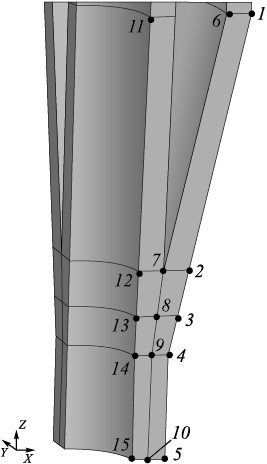
The calculation results are presented along the lines passing through specific points (Fig. 3), located in the Y plane at Y = 0.
Fig. 3. Position of the points to represent the calculation results |
The compression force exerted by the striker along the X-axis amounts to 722 MPa, along the Y-axis it measures 399 MPa, and the pulling force along the Z-axis is 42 MPa.
The calculation results are tabulated in the following table, specifying the particular values of displacements and stresses at points 1 – 15. Since the maximum and minimum values of these parameters do not consistently correspond to points 1 and 15, the maximum and minimum displacements and stresses along these three lines are additionally provided.
Results of calculation of displacements and stresses
| ||||||||||||||||||||||||||||||||||||||||||||||||||||||||||||||||||||||||||||||||||||||||||||||||||||||||||||||||||||||||||||||||||||||||||||||||||||||||||||||||||||||||||||||||||||||||||||||||||||||||||||||||||||||||||||||||||||||||||
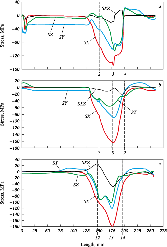
The distribution of stresses in the deformation zones along the three reference axes (SX, SY, SZ) is illustrated in Figure 4, depicting the compression of the billet by the striker by 5 mm while simultaneously lowering the striker by 5 mm, with the working surface of the striker oriented along the fixed radius.
Fig. 4. Nature of stresses along the line drawn |
The axial stress diagrams reveal that, as the strikers compress the hollow billet, the maximum compressive stress SX reaches –147.9 MPa on their contact surface at point 3. Concurrently, stresses SY and SZ are significantly lower or equal to –102.2 and –86.4 MPa (Fig. 4). The highest shear stress, SXZ, at point 3 is 19.8 MPa. As we move along the line where the wall crusts of the hollow billet meet, the nature of axial stresses changes. The highest value, which is –164.6 MPa, corresponds to stress SX at point 8, while stresses along the other reference axes are notably lower (Fig. 4, b and Table). It’s worth noting that the maximum axial stresses, SX, SY and SZ, are observed on the contact surface of the billet with the mandrel at point 13, with values of –179.0, –116.4 and –102.4 MPa, respectively (Fig. 4, c). Additionally, the maximum shear stress is also located at this point, measuring 44.6 MPa.
The results presented demonstrate that during the cyclic deformation of the hardened steel shell wall by the strikers, significant compression stresses, reaching up to –179.0 MPa, occur along all three reference axes. This indicates that the shell wall, when compressed by calibrated strikers, experiences nearly uniform compression from all directions. This is particularly significant when processing continuously cast metal to produce high-quality steel hollow billets [17 – 20].
Conclusion
The article details a new technology for producing hollow steel billets using a resource-efficient and compact unit for combined continuous casting and deformation. The study revealed distinct patterns in metal displacements and axial stresses within the cyclic deformation zones during the production of hollow steel billets using the unit. It was observed that when the wall of a hollow billet undergoes deformation, the metal experiences uniform compression from all directions. This phenomenon greatly contributes to the production of high-quality steel pipe billets.
References
1. Lekhov O.S., Mikhalev A.V. Unit of Continuous Casting and Deformation for Production of Steel Sheets and Billets. Moscow: Vologda: Infra-Inzheneriya; 2021:304. (In Russ.).
2. Lekhov O.S., Guzanov B.N., Lisin I.V., Bilalov D.Kh. Investigation of the combined process of continuous casting and cyclic deformation for the production of steel sheets. Stal’. 2016;(1):59–62. (In Russ.).
3. Fujii Н., Ohashi Т., Hiromoto Т. On the formation of the internal cracks in continuously cast slabs. Tetsu-to-Hagane. 1978;18(8):510–518. https://doi.org/10.2355/tetsutohagane1955.62.14_1813
4. Lekhov O.S., Mikhalev A.V., Shevelev M.M. Load and strain status of CCM backups and stripe deformation at production of steel sheets for welded pipes. Report 1. Izvestiya. Ferrous Metallurgy. 2018;61(4):268–273. (In Russ.). https://doi.org/10.17073/0368-0797-2018-4-268-273
5. Sorimachi K., Emi Т. Elastoplastic stress analysis of bulging as a major cause of internal cracks in continuously cast slabs. Tetsu-to-Hagane. 1977;63(8):1297–1304. https://doi.org/10.2355/tetsutohagane1955.63.8_1297
6. Vyunnenberg K. Production of continuously cast blanks that meet the highest quality requirements. In: Proceedings of the Sixth Int. Congress of Iron and Steel. Vol. 3. Мoscow: Mashinostroenie; 1990:364–376. (In Russ.).
7. ANSYS. Structural Analysis Guide. Rel. 15.0.
8. Bogatov A.A., Nukhov D.Sh., P’yankov K.P. Finite element modeling of plate rolling. Metallurg. 2015;(2):19–23. (In Russ.).
9. Takashima Y., Yanagimoto I. Finite element analysis of flange spread behavior in H-beam universal rolling. Steel Research International. 2011;82(10):1240–1247. https://doi.org/10.1002/srin.201100078
10. Karrech A., Seibi A. Analytical model of the expansion in of tubes under tension. Journal of Materials Processing Technology. 2010;210:336–362.
11. Kazakov A.L., Spevak L.F. Numeral and analytical studies of nonlinear parabolic equation with boundary conditions of a special form. Applied Mathematical Modelling. 2013;37(10-13):
12. –6928. https://doi.org/10.1016/j.apm.2013.02.026
13. Kobayashi S., Oh S.-I., Altan T. Metal Forming and Finite-Element Method. New York: Oxford University Press; 1989:377.
14. Jansson N. Optimized sparse matrix assembly in finite element solvers with one-sided communication. High Performance Computing for Computational Science – VECPAR 2012. Springer: Berlin, Heidelberg; 2013:128–139.
15. Matsumia Т., Nakamura Y. Mathematical model of slab bulging during continuous casting. In: Applied Mathematical and Physical Models in Iron and Steel Industry. Proceedings of the 3rd Process Technological Conference, Pittsburgh, Pa, 28–31 March 1982. New York: 1982:264–270.
16. Park C.Y., Yang D.Y. A study of void crushing in large forgings: II. Estimation of bonding efficiency by finite-element analysis. Journal of Materials Processing Technology. 1997;72(1):32–41.
17. Efimenko L.A., Prygaev A.K. Determination of Actual Mechanical Properties of Pipeline Metal Based on Hardness Measurement. Moscow: Izd-vo RTU nefti i gaza; 2007:18. (In Russ.).
18. Kudrya A.V. Critical factors of metallurgical quality of high-strength steels. In: Perspective Materials. Vol. V. Tol’yatti: izd. TSU; 2013:332–362. (In Russ.).
19. Kazakov A.A., Kiselev D.V. Modern methods for assessing the quality of materials structure based on panoramic studies with TXIXOMET image analyzer. In: Perspective Materials. Vol. V. Tol’yatti: izd. TSU; 2013:270–329. (In Russ.).
20. Kyung-Moon L., Hu-Chul L. Grain refinement and mechanical properties of asymmetrically rolled low carbon steel. Journal of Materials Processing Technology. 2010;210(12):1574–1579. https://doi.org/10.1016/j.jmatprotec.2010.05.004
21. Efron L.I. Metal Science in “Big” Metallurgy. Pipe Steels. Moscow: Metallurgizdat; 2012:696. (In Russ.).
22.
About the Authors
O. S. LekhovRussian Federation
Oleg S. Lekhov, Dr. Sci. (Eng.), Prof. of the Chair of Engineering and Vocational Training in Machinery and Metallurgy
11 Mashinostroitelei Str., Yekaterinburg 620012, Russian Federation
A. V. Mikhalev
Russian Federation
Aleksandr V. Mikhalev, Cand. Sci. (Eng.), General Director
28 Sakko i Vantsetti Str., Pervouralsk, Sverdlovsk Region 623107, Russian Federation
S. O. Nepryakhin
Russian Federation
Sergei O. Nepryakhin, Cand. Sci. (Eng.), Assist. Prof. of the Chair “Metal Forming”
28 Mira Str., Yekaterinburg 620002, Russian Federation
Review
For citations:
Lekhov O.S., Mikhalev A.V., Nepryakhin S.O. Stress state of billet – mandrel system during production of hollow steel billet in a unit for continuous casting and deformation. Part 1. Izvestiya. Ferrous Metallurgy. 2023;66(4):485-491. https://doi.org/10.17073/0368-0797-2023-4-485-491


