Scroll to:
Parametric model of a three-roll unit of radial-shear rolling mini-mill
https://doi.org/10.17073/0368-0797-2023-3-376-386
Abstract
The article discusses the main structural features of radial-shear rolling mini-mills and their most common sizes. A generalized algorithm for designing such mills using modern CAD systems is described. The main approaches to the methodology of software adaptive design of models in engineering are listed with their features and differences. In particular, the methodology of horizontal modeling, explicit modeling methodology, and resilient modeling strategy are considered. The article describes the method of virtual squeezes and presents the main geometric scheme of the spatial position of the rollers of the longitudinal profile. The data obtained as a result of the calculations were encoded and summarized in tables. The formulas presented were used in the parametric design of the roller unit of the three-roller mill 30-70 using Autodesk Inventor software. The obtained parametric model, using classical formulas of the virtual squeezes method, allows for automatic reconstruction of the deformation zone for new initial parameters. The developed model is applicable for three-roller mills with working roll angles δ = 5 – 15° and feed angles β = 18 – 22°. The article presents sketches and diagrams of the constructed model for different rolling angles – 5, 10, and 15°. As the rolling angle increases, a noticeable increase in the conicity of the roller is observed. The vector of future research on improving the obtained software model was indicated. Further research on improving the parametric model will include expanding the set of existing parameters to include the frame and full set of roller connections – neck, cover, pressing device, etc.
Keywords
For citations:
Troitskii D.V., Gamin Yu.V., Galkin S.P., Budnikov A.S. Parametric model of a three-roll unit of radial-shear rolling mini-mill. Izvestiya. Ferrous Metallurgy. 2023;66(3):376-386. https://doi.org/10.17073/0368-0797-2023-3-376-386
Introduction
Modern radial shear rolling (RSR) mini-mills are characterized by a simple design, utilizing optimal feed angles (18 – 22°) and rolling angles (not exceeding 10 – 12°) [1]. Typically, these mills are specifically assembled for the production of particular products, determined by the mill’s dimensions and structural features. Despite their compactness and high mobility, these mills offer a wide range of full-scale capabilities. Helical rolling mini-mills align with the requirements of lean production [2] and facilitate the application of innovative RSR methods, which enhance the material properties of long products through intensive plastic deformation [3; 4]. For example, pure magnesium has shown significant improvement in its mechanical properties through three roller helical rolling, attributed to changes in its microstructure [5]. Researchers in [6; 7] have documented the formation of a gradient structure and the improved properties of austenite stainless steel AISI 321. The technological capabilities of RSR mini-mills have been successfully tested using titanium rods in accordance with specific requirements [8].
For example, the «30-80» three-roller piercing mini-mill is specifically designed for hot piercing of ingots into shell with a bottom [9 – 11]. It utilized a wedge lock device as a screw-down mechanism, and the rollers are characterized by pre-feed and rolling angles according to the design. The mini-mill stands out for its mobility, compactness, and the absence of the need for assembly on a power basement.
Furthermore, numerous industrial and research entities have successfully implemented the «14-40» three-roller helical mini-mills [1; 12]. A comprehensive overview of the main designs and specifications of RSR mini-mills can be found in [1]. These new-generation mini-mills exhibit lower metal intensity, reduced energy consumption, and offer simplified operation compared to small section mills using longitudinal rolling techniques. This makes them particularly attractive to small and medium-sized companies operating in the metallurgy and mechanical engineering sectors.
Previously, researchers [13 – 15] developed a systematic approach to the design of mill stand based on the unified “metal deformation–mill design” system, enabling the production of items with predetermined properties.
The new mill stand designs are based on several key principles: the use of a close-top roll housing, positioning the working rollers at consistent angles of feed and rolling, and separation the actuating mechanism of roller positioning from direct action of the rolling force. These design principles have not only simplified the mini-mill design but also improved its operational conditions.
Typically, the design process for such mills begins with the deformation zone and the predetermined main geometrical profiles of the rollers and rolled ingots. Given the wide range of dimensions for RSR mills and the need to design custom equipment to meet specific customer demands, it is advisable to utilize the parametrization capabilities available in most modern CAD systems during the design process. These capabilities significantly reduce the time required for developing computer models and facilitate subsequent refinement and error elimination.
Modern CAD systems offer parameterization capabilities, allowing for the creation of a wide range of parameters. These parameters can be static (representing a fixed value), calculated (expressed through mathematical equations based on static parameters), or reference (referring to the actual value of existing geometry for use in other geometrical units). CAD systems enable the establishment of semantic connections between constructed geometry and developed parameters of any type, thereby creating associative bonds between different components of the designed equipment.
The choice and implementation of an appropriate design methodology play a crucial role in the design process. A well-defined methodology allows for the development of a unified approach to constructing associative bonds and establishing parametric dependencies between individual units [16]. This formalization of parametric simulation methods brings the design process closer to the original intent of the engineer [17], promotes standardization and internal consistency within the simulated model, reduces development time, and maximizes the potential for reusing previously developed parts and units. Employing an appropriate and well-designed methodology enables faster modifications of models compared to an informal approach [18; 19]. The development of design methods is closely tied to the advancement of CAD systems and their application in engineering design tasks. Ultimately, these methods represent the accumulated engineering experience of researchers aimed at enhancing the flexibility and validity of the designed models [20]. An incorrect or non-formalized methodology can have a negative impact on the overall quality of the model and the time required for the design process [21]. There are documented cases where the correct selection of a methodology, particularly in the context of MDO (Multidisciplinary design optimization) tasks, has led to significant achievements in aircraft production [22].
There are three formalized methodologies known for developing computer models, aimed at enhancing model flexibility, reduction development and modification time, and improving overall model stability.
Horizontal Modeling methodology: This simulation strategy, patented by Delphi Technologies [23], focuses on reducing critical errors that may arise during model modification by elimination of dependences in the existing geometry and parameters. Traditional CAD systems typically employ a vertical tree structure for elements, which can lead to errors when modifications are made. The Horizontal Modeling Methodology proposes minimizing such dependencies and instead referring to unaffected initial elements, such as basic planes and the center of coordinates. This transforms the vertical tree structure into a horizontal one, reducing the occurrence of errors.
Explicit Reference Modelling methodology (ERM): Proposed in [18], ERM aims to minimize the number of dependencies and restrictions related to the current geometry in the model, as it tends to vary with changes in the model. Instead, references are used, which can refer to auxiliary geometric objects. Unlike the Horizontal Modeling Methodology, ERM is focused on maintaining the global concept of parametrical approach.
Resilient Modeling methodology [24] was introduced in [25]. This methodology emphasizes the creation of robust models with extensive possibilities for reusing units and elements. It involves optimizing parent-child dependencies and organizing the structure of elements in a more comprehensible manner.
Each of these methodologies has its advantages and disadvantages depending on the pattern of the developed model. The key criterion for the operability of a parametric model is its ability to adapt to changes made to its elements. The operability of these methodologies has been demonstrated in various optimization scenarios, including the automatic generation of numerous geometrical variations and units [26].
This work focuses on the parametric simulation of a roller unit using generalized algorithm for designing of deformation zone of a three-roller RSR mill in Autodesk Inventor software. The model is developed following the recommendations of the Explicit Reference Modelling.
Formulation of the problem and experimental methods
Geometry of the spatial position of longitudinal profile rolls
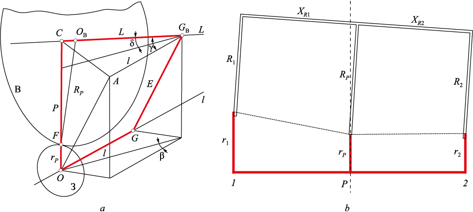
In order to construct and calculate the geometry of the spatial position of longitudinal profile rollers, a procedure known as virtual squeezes is utilized, which was developed and proposed for calculations of RSR mini-mills [13]. This procedure is based on invariant geometry relations of RSR mills, taking into account changes in virtual angles of feed and rolling along the axis of the deformation zone. It allows for efficient parametrization of roller dimensions and the deformation zone [14]. The procedure is based on the layout depicted in Fig. 1, a, where:
– З represents the considered cross section of the ingot with radius rP and center at О;
– В represents the cross section of the roller with radius RP and center at ОВ , in contact with the ingot cross section З at point F;
– Ol and CL are the rolling axes for the ingot and the deformation area, respectively;
– GGB is the common perpendicular (eccentricate) with length Е to the roller and rolling axes, meaning \(\angle \)OGGB = \(\angle \)CGBG = 90°;
– ОС is the line perpendicular to the rolling axis with length Р, intersecting the roller axis, denoted as \(\angle \)СOG = 90°. In drum type mills, it is positioned on the drum axis;
– β, δ, γ represent the angles of feed, rolling and crossing, respectively.
Fig. 1. Diagram of the relative position of the axes of roll CL and rolling Ol (a); |
The set of notions used, such as technological squeeze, geometrical squeeze, and design layout, were introduces in [27; 28]. According to the procedure, the determination of the roller profile is simplified to calculating the radius of the roller’s cross section that will come into contact with the ingot’s cross section of a known radius ri . This contact point is located at a known distance Δli along the rolling axis from the technological squeeze (from point О) (Fig. 1, b).
Calculation of roll calibration using the deformation center
Now, let us illustrate the calculations based on the procedure by determining the roller radius in extreme cross section of the deformation zone using the initial data for «30-70» mill (Table 1). The roller diameter in the squeeze is chosen to ensure the minimum pass without the roller surface crossing. The maximum feasible roller diameter in the squeeze, taking into account the feed and rolling angles, as well as the gap between rollers, is determined by the equation [29]
| \[D_{\rm{в}}^{\max } = \frac{{d_{\rm{к}}^{\min } - \frac{\Delta }{{\cos \varphi }}}}{k},\] | (1) |
where \(D_{\rm{в}}^{\max }\) is the maximum possible diameter in the squeeze, mm; \(d_{\rm{к}}^{\min }\) is the minimum roller pass diameter in the squeeze, mm; Δ is the gap between adjacent rollers, mm; φ is the inclination angle of the generator of the input roller cone, deg; k is the coefficient that relates the roller diameter to the pass diameter.
Table 1. Source data for the calculation example
| |||||||||||||||||||||||||||||||||||||||||||||||||||||||||||||||||||||||||||||||||||||||||||||||||||||||||
The coefficient k incorporates parameters such as the feed angle β, rolling angle δ and the number of operating rollers, and can be determined using the equation:
| \[k = \frac{{\cos \delta - 0.87\sqrt {0.75\cos {\delta ^2} + 0.25\cos {\beta ^2}} }}{{\cos \delta \sqrt {0.57\cos {\delta ^2} + 0.19\cos {\beta ^2}} }}.\] | (2) |
These conditions are subsequently verified by analyzing interference in the CAD system.
The calculated data obtained are sufficient for plotting the roller calibration for three cross sections The calculated results are summarized in Table 2.
Table 2. Results of calculation of calibration parameters for three sections
| |||||||||||||||||||||||||||||||
Similar calculations for roller unit calibration can be based on a higher number of cross sections to achieve greater precision. The calculation process for each cross section is similar to the aforementioned procedure. By using the described algorithm, it is possible to create a table of roller calibration with required step for production using a numerically controlled machine.
Key experimental findings
The Explicit Reference Modeling methodology was chosen as the foundation for this work. All calculated parameters from Tables 1 and 2 were incorporated as user parameters into the Autodesk Inventor models. These parameters are directly calculated and determined within the Autodesk Inventor software.
To simplify the calculations within Autodesk Inventor, all the parameters are encoded as two-symbol variables (consisting of a Latin letter and a digit). The parameters are categorized as follows:
– parameters X: these serve as the main initial data for the model calculation;
– parameters A: these are used to determine the parameters of technological and geometrical squeezes;
– parameters B: these are used to determine the parameters of the virtual squeeze in cross section 1 of the deformation zone input;
– parameters C: these are used to determine the parameters of the virtual squeeze in cross section 2 of the deformation zone output.
A comprehensive list of the parameters is provided in Table 3.
Table 3. Parameter coding table
| |||||||||||||||||||||||||||||||||||||||||||||||||||||||||||||||||||||||||||||||||||||||||||||||||||||||||||||||||||||||||||||||||||||||||||||||||||||||||||||||||||||||||||||||||||||||||||||||||||||||||||||||||||||||||||||||||||||||||||||||||||||||||||||||||||||||||||||||||||||||||||||||||||||||||||||||||||||||||||||||||||||||||||||||||||||||||||||||||||||||||||||||||||||||||||||||||
The accuracy of the constructed model is verified using the parameters X1, X2, A2, B5, B6, C5 and C7. The following relationship holds true for these parameters:
| cosX1 cosX2 = cosB5 cosB6 = cosC5 cosC7 = cosA2. | (3) |
The deformation zone in the model is created using a 3D sketch. The explicit parameters of this sketch are linked to the user-defined parameters. When the dependencies and initial data (X) are correctly established, the 3D sketch of the model will have zero degrees of freedom. This means that the constructed geometry variant is the only possible one given the preset parameters. Removing any initial parameter (X) will introduce degrees of freedom to the deformation zone model.
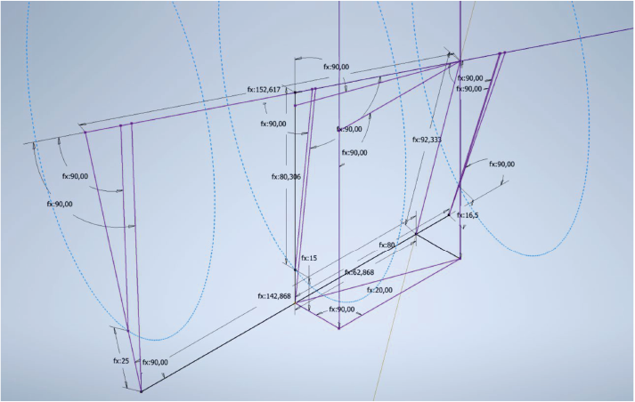
The layout of the mutual position of the roller and rolling axes is depicted in Fig. 2.
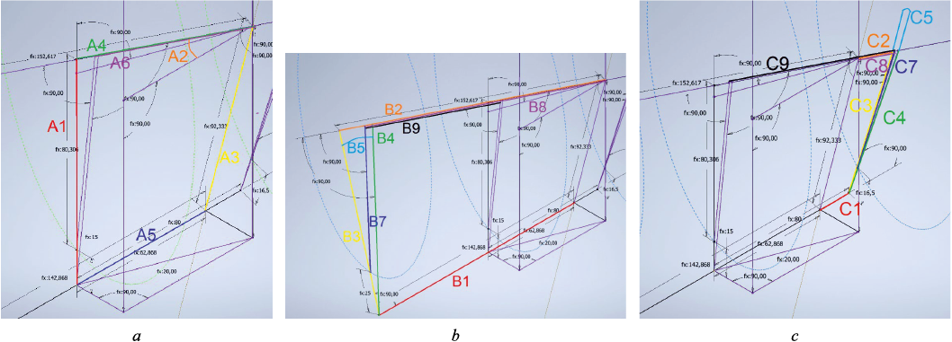
Fig. 3 illustrates the parameters A, B, C, which are used to construct the geometrical and technological roller squeezes.
Fig. 2. Adaptive scheme of relative position of the axes of roll and rolling (β = 20°, δ = 5°)
Fig. 3. Parameters used to construct geometric sections: A (a), B (b), C (с) |
The deformation zone is constructed starting from the technological squeeze on the rolling axis, which serves as the common coordinate center of the model O. The rolling axis is plotted passing through the coordinate center. The distance l between technological and geometrical squeezes along the rolling axis (parameter A5) is determined to obtain segment OG. An auxiliary line is drawn from the point O, perpendicular to segment OG. Along this line, the rod radius in the squeeze rP and the roller radius in the squeeze RP are consecutively plotted (parameters X4 and X3, respectively) to obtain the point C. The segment CGB (А4) coincides with the roller axis. Perpendiculars from segment OG are used to construct the feed angle β (parameter X1). Another auxiliary line is drawn from the top of angle β, parallel to segment ОС. Point GB is obtained by intersecting this auxiliary line with the perpendicular. The eccentricate E (parameter A3) is plotted from point G to intersect the auxiliary line. The construction of the other virtual squeezes follows a similar procedure.
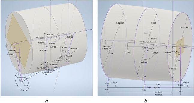
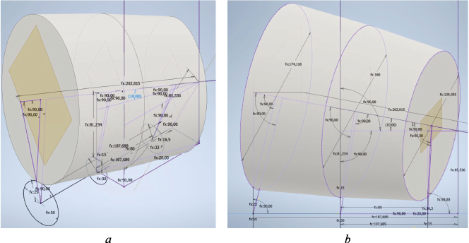
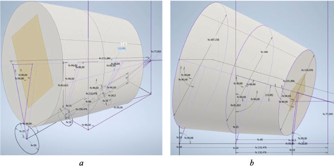
Figures 4–6 depict the parametric models of constructed roller–body assemblies for various mill dimensions.
Fig. 4. Adaptive model of the constructed roll-barrel 30-70 with a rolling angle δ = 5°:
Fig. 5. Adaptive model of the constructed roll-barrel 30-70 with a rolling angle δ = 10°:
Fig. 6. Adaptive model of the constructed roll-barrel 30-70 with a rolling angle δ = 15°: |
These models can be used to simulate the deformation zone and design roller parts for three-roller mini-mills. The developed parametric model is suitable for three-roller mills with rolling angles of working rollers δ ranging from 5 to 15° and feed angles δ ranging from 18 to 22°.
Notable features of these models include fast construction and reconstruction of roller joints using parametrization. By employing universal modular joints between individual parameters of each model and mini-mill units, the design time for mills can be significantly reduced. Additionally, the constructed model ensures the production of high-quality items based on the specified initial model parameters (X).
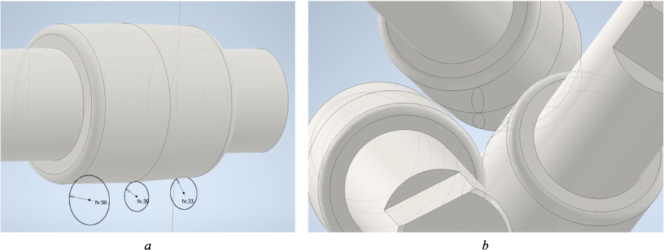
Fig. 7 illustrates the deformation zone consisting of three rollers. The deformation zone can be obtained by utilizing a circular array or creating an assembly by positioning the rollers around the sketch at a 120° angle, in accordance with the preset rolling and feed angles.
Fig. 7. Constructed parametric model of deformation focus: roll joint constructed |
The parametrization method greatly facilitates the design process of roller joints and rolling mills, reducing the manual effort required for adjusting parts and angle ratios.
Conclusions
By applying a parameterizable design algorithm, engineers can efficiently develop a computer model. Specifically, the method for plotting the deformation zone, based on the radii of the rolled ingot, roller, feed angle, and rolling angle, enables the rapid creation of a 3D model for roller calibration and the deformation zone. This model serves as a foundation for selecting other structural units of the mill.
The algorithm for designing the deformation zone was developed as a function of adjustable parameters, which are utilized for parametrization within a CAD system. The algorithm is based on the concept of virtual squeezes, which leverage the invariant relationships of RSR roller geometry in relation to the desired parameters of the technological squeeze. These parameters include the diameters of the roller and rod, as well as the feed and rolling angles along the rolling axis and/or roller axis. In the development of the computer model for the roll joint of the “30-70” mill, an explicit reference simulation methodology was employed, incorporating parameterizable properties that can be varied based on the mill’s objectives and specific design requirements. The resulting model is adaptive, allowing for the easy determination of dimensions and spatial positions of rollers and the deformation zone in the mini-mill.
Further research efforts will focus on the development of an adaptive parametric model, encompassing the assembly of component units such as the shaft and body of working roller, bearing supports, pads, screw-down mechanism, and stands.
References
1. Galkin S.P., Gamin Yu.V., Aleshchenko A.S., Romantsev B.A. Modern development of elements of radial shift rolling theory, technology, and mini-rolling. Chernye metally. 2021;(12). (In Russ.). https://doi.org/10.17580/chm.2021.12.09
2. Galkin S.P. Radial shear rolling as an optimal technology for lean production. Steel in Translation. 2014;44(1):61-64. https://doi.org/10.3103/S0967091214010069
3. Naizabekov A., Lezhnev S., Arbuz A., Panin E., Koinov T. Simulation of radial-shear rolling of austenitic stainless steel AISI-321. Journal of Chemical Technology and Metallurgy. 2019;54(5):1086–1094.
4. Arbuz A., Kawalek A., Ozhmegov K., Panin E., Magzhanov M., Lutchenko N., Yurchenko V. Obtaining an equiaxed ultrafine-grained state of the longlength bulk zirconium alloy bars by extralarge shear deformations with a vortex metal flow. Materials. 2023;16(3):1062. https://doi.org/10.3390/ma16031062
5. Mashekov S., Smailova G., Alshynova A., Uderbayeva A., Sembaev N., Zhauyt A. Structure formation of aluminum alloy D16 while rolling bars in the radial shear mill. Metalurgija. 2020;59(2):195–198.
6. Diez M., Kim H.-E., Serebryany V., Dobatkin S., Estrin Y. Improving the mechanical properties of pure magnesium by three-roll planetary milling. Materials Science and Engineering: A. 2014;612:287–292. https://doi.org/10.1016/j.msea.2014.06.061
7. Naizabekov A., Lezhnev S., Panin E. Formation of a gradient structure in austenitic stainless steel AISI 321 by radial-shear rolling. Solid State Phenomena. 2021;316:246–251. https://doi.org/10.4028/www.scientific.net/ssp.316.246
8. Negodin D.A., Galkin S.P., Kharitonov E.A., Karpov B.V., Khar’kovskii D.N., Dubovitskaya I.A., Patrin P.V. Testing of radial-shear rolling technology and pre-project selection of mini rolling mills for flexible production of titanium rods of small cross sections in conditions of JSC “CMP”. Metallurg. 2018;(11):40–46. (In Russ.).
9. Mishin I., Naydenkin E., Ratochka I., Lykova O., Vinokurov V., Manisheva A. Effect of radial shear rolling and aging on the structure and mechanical properties of titanium alloy VT35. AIP Conference Proceedings. 2020;2310(1):020206. https://doi.org/10.1063/5.0034081
10. Shatalov R., Medvedev V., Bogdanov S. Development and use of an electromagnetic unit for controlling the mechanical properties along the steel vessel height at the exit from a rolling–pressing line. Russian Metallurgy (Metally). 2022;2022(6):628–633. https://doi.org/10.1134/S0036029522060210
11. Shatalov R., Medvedev V. Effect of deformed workpiece temperature inhomogeneity on mechanical properties of thin-walled steel vessels during treatment in a rolling and pressing line. Metallurgist. 2019;63(1–2):176–182. https://doi.org/10.1007/s11015-019-00807-w
12. Stefanik A., Szota P., Mróz S. Analysis of the effect of rolling speed on the capability to produce bimodal-structure AZ31 alloy bars in the three-high skew rolling mill. Archives of Metallurgy and Materials. 2020;65(1):329–335. https://doi.org/10.24425/amm.2020.131734
13. Galkin S.P., Fadeev V.A., Gusak A.Yu. Methodology of virtual squeezing for calculation of mini-mills of shear-radial (helical) rolling. Proizvodstvo prokata. 2016;(2):27–35. (In Russ.).
14. Galkin S.P., Fadeev V.A., Gusak A.Yu. Comparative analysis of geometry of mini-mills of radial-shear (helical) rolling. Proizvodstvo prokata. 2015;(12):19–25. (In Russ.).
15. Belevich A.V., Goncharuk A.V., Daeva E., Romantsev B.A. Study of technological and structural parameters of helical working stands with the help of modern finite element systems. Izvestiya. Ferrous Metallurgy. 2002;45(9):32–35.
16. Company P., Naya F., Contero M., Camba D.J. On the role of geometric constraints to support design intent communication and model reusability. Computer-Aided Design & Applications. 2020;17(1):61–76. https://doi.org/10.14733/cadaps.2020.61-76
17. Otey J., Company P., Contero M, Camba D.J. Revisiting the design intent concept in the context of mechanical CAD education. Computer-Aided Design & Applications. 2018;15(1):47–60. https://doi.org/10.1080/16864360.2017.1353733
18. Bodein Y., Rose B., Caillaud E. Explicit reference modeling methodology in parametric CAD system. Computers in Industry. 2014;65(1):136–147. https://doi.org/10.1016/j.compind.2013.08.004
19. Camba J.D., Contero M., Company P. Parametric CAD modeling: An analysis of strategies for design reusability. Computer-Aided Design. 2016;74:18–31. https://doi.org/10.1016/j.cad.2016.01.003
20. Cheng Z., Ma Y. A functional feature modeling method. Advanced Engineering Informatics. 2017;33:1–15. https://doi.org/10.1016/j.aei.2017.04.003
21. Aranburu A., Justel D., Contero M., Camba J.D. Geometric variability in parametric 3D models: Implications for engineering design. Procedia CIRP. 2022;109:383–388. https://doi.org/10.1016/j.procir.2022.05.266
22. Amadori K., Tarkian M., Ölvander J., Krus P. Flexible and robust CAD models for design automation. Advanced Engineering Informatics. 2012;26(2):180–195. https://doi.org/10.1016/j.aei.2012.01.004
23. Landers D.M., Khurana P. Horizontally-structured CAD/CAM modeling for virtual concurrent product and process design. Patent no. US6775581B2 USA. 10.08.2004.
24. Resilient Modeling Strategy. 2018; URL: https://www.resilientmodeling.net (Дата обращения: 15.12.2022)
25. Gebhard R. A resilient modeling strategy. Solid Edge University 2013. Siemens; 2013.
26. Aranburu A., Cotillas J., Justel D., Contero D., Camba D.J. How does the modeling strategy influence design optimization and the automatic generation of parametric geometry variations? Computer-Aided Design. 2022;151:103364. https://doi.org/10.1016/j.cad.2022.103364
27. Mironov Yu.M. Geometric parameters of skew rolling. Proizvodstvo trub. 1962;(6):37–46. (In Russ.).
28. Teterin P.K. Theory of Cross Rolling. Moscow: Metallurgiya; 1971:386.
29. Budnikov A.S. Improvement of tube rolling and sizing processes in three-roller helical rolling mills: Cand. Tech. Sci. Diss. Moscow; 2020:147. (In Russ.).
About the Authors
D. V. TroitskiiRussian Federation
Daniil V. Troitskii, Postgraduate of the Chair “Metal Forming”
4 Leninskii Ave., Moscow 119049, Russian Federation
Yu. V. Gamin
Russian Federation
Yurii V. Gamin, Cand. Sci. (Eng.), Assist. Prof. of the Chair “Metal Forming”
4 Leninskii Ave., Moscow 119049, Russian Federation
S. P. Galkin
Russian Federation
Sergei P. Galkin, Dr. Sci. (Eng.), Prof. of the Chair “Metal Forming”
4 Leninskii Ave., Moscow 119049, Russian Federation
A. S. Budnikov
Russian Federation
Aleksei S. Budnikov, Cand. Sci. (Eng.), Assist. Prof. of the Chair “Metal Forming”
4 Leninskii Ave., Moscow 119049, Russian Federation
Review
For citations:
Troitskii D.V., Gamin Yu.V., Galkin S.P., Budnikov A.S. Parametric model of a three-roll unit of radial-shear rolling mini-mill. Izvestiya. Ferrous Metallurgy. 2023;66(3):376-386. https://doi.org/10.17073/0368-0797-2023-3-376-386


