Scroll to:
Modeling and optimization of the effect of temperature seams on stress-strain state of spherical metal casting molds
https://doi.org/10.17073/0368-0797-2025-4-372-382
Abstract
The objective of this theoretical study is to evaluate the effect of annular temperature seams in the inner surface of a spherical metal casting mold on the level of stress-strain state (SSS) in it during crystallization of a steel casting. The specificity of this technological process consists in the geometric shape (sphere) of the casting model, when the crystallizing metal creates significant compressive stresses in the inner surface of the mold (in the first moments), which are enhanced by the mold curvature: the mold inner layer, heating up, tries to increase in volume, but this is prevented not only by the cooler outer layers, but also by curvature of the surface layer itself. Two possible applications of the casting mold are being considered: with and without seams. The problem of optimizing the design parameters of temperature seams (recesses) is formulated. It depends on the magnitude of the normal stresses occurring in the casting mold at the initial stage of the steel casting crystallization. When solving the problem, the equations of the linear theory of elasticity, the equations of thermal conductivity and the proven numerical method are used. The paper presents a numerical scheme and a developed algorithm for solving the problem. Crack resistance was estimated based on the magnitude of normal stresses in a spherical metal mold. The optimal design options (schemes) of a spherical metal casting mold found as a result of solving the test problem depend on location of the temperature seams in the shell mold, the stress values in them under conditions of the min-max objective function and the developed algorithm. The results of solving the problem are presented graphically in the form of plots of stresses and temperatures in the studied area in different sections and periods of cooling of the shell mold and the metal growing crust. The obtained results of resistance of a metal spherical casting mold were analyzed.
For citations:
Evstigneev A.I., Chernyshova D.V., Odinokov V.I., Dmitriev E.A., Evstigneeva A.A., Koloshenko Yu.B., Potyanikhin D.A. Modeling and optimization of the effect of temperature seams on stress-strain state of spherical metal casting molds. Izvestiya. Ferrous Metallurgy. 2025;68(4):372-382. https://doi.org/10.17073/0368-0797-2025-4-372-382
Introduction
Metal casting molds are widely used in foundry production across various casting methods, including permanent mold casting, centrifugal casting, die casting, continuous casting, liquid forging, and others. A major drawback of these casting methods is the limited service life of metal molds due to the combined effects of mechanical and thermal loads. These loads lead to elevated stress–strain states (SSS) within the molds, which can result in structural fracture or deformation of the mold geometry due to thermal stresses. To mitigate these effects, various technological and design solutions are implemented in practice.
Both the analysis of the literature and practical experience indicate that the geometry of the casting produced in the mold significantly affects mold resistance. Among all geometries, the spherical (ball-shaped) casting is considered the most unpredictable in terms of mold resistance.
In industrial production of spherical castings, different types of casting molds are used, including expendable sand–clay molds, ceramic molds, and split metal molds. These molds are subjected to varying degrees of mechanical and thermal loads, which may lead to structural degradation or reduced operational life.
A theoretical concept and a fundamentally new technological solution1 were proposed by the authors of [1] to improve the resistance of spherical ceramic shell molds (SMs) by introducing annular temperature seams on the inner surface of the mold. This idea emerged from the analysis of a well-known foundry technique used to reduce thermal stresses in castings – namely, the use of “stiffening ribs” [2]. In the context of this study, annular temperature seams (recesses) serve a similar purpose. An annular temperature seam is a ring-shaped recess located on the inner surface of the ceramic shell mold.
The evolution of the SSS in metal molds during permanent mold casting has been discussed in detail in articles [3; 4].
The SSS of permanent molds is evaluated using the finite element method [3] in two stages: first, solving the heat conduction problem; and second, solving the elastoplastic deformation problem using the obtained temperature fields. The simulation results enabled the design and implementation of new, more durable cast iron molds with reduced weight.
Reference [4] presents data on numerical modeling of casting formation processes in metal molds. The finite difference method was used as the computational foundation, specifically in the form of an explicit difference scheme. A rectangular spatial grid within the mold base was employed to simulate heat transfer in the system. Grid spacing in the solidifying casting, mold wall, and insulation layer was coordinated with the thermophysical properties of the base to ensure thermal uniformity. Computational stability was maintained by choosing a time step of \(\bar \Delta \)τ ≤ 30 s, under which the Fourier number did not exceed its critical value. The problem was formulated in two dimensions.
The modeling results for the SSS in a solidifying steel casting [5; 6] made it possible to predict crack formation. The development of these cracks depends not only on temperature fields and the resulting thermal stresses and strains but also on the localization of shrinkage porosity.
In [7], a general expression was derived for calculating shrinkage and thermal stresses in an elastoplastic sphere caused by a spherically symmetric heat source. The expression accommodates arbitrary nonlinear hardening laws and includes elastic unloading of the elastoplastic sphere.
Study [8] examined elastoplastic and residual stresses in a thick-walled spherical vessel subjected to external hydrostatic pressure. The findings led to the development of a process for inducing favorable compressive residual stresses in the inner regions of cylindrical and spherical vessels.
The subject of [9] was a functionally graded hollow sphere with spherical isotropy under internal pressure. The goal was to achieve a favorable stress distribution in the hollow sphere subjected to internal pressure, accounting for both ductile and brittle material behavior.
In [10], a transient thermoelastic analysis was conducted for a multilayered hollow cylinder with piecewise power-law material inhomogeneity, subjected to asymmetric surface heating. The study examined the influence of functional grading on the development of thermal stresses.
A numerical simulation was carried out in ANSYS Mechanical [11] for a two-layer thick-walled spherical shell under combined thermal and mechanical loading [11].
Reference [12] presented the solution to a problem involving stresses and displacements in a thick spherical shell subjected to internal and external pressure [12].
Based on plane elasticity theory [13] derived the displacement and stress components in thick-walled spherical pressure vessels made of inhomogeneous materials exposed to both internal and external pressure. The influence of material inhomogeneity on elastic deformations and stress distribution was evaluated.
The structural optimization of a three-layer cylinder assembled by thermal shrink-fitting from different materials and subjected to very high internal pressure was investigated in [14].
In [15], axisymmetric modeling of a multilayer shell was performed. A plane strain problem was solved for a cylinder surrounded by concentric ring layers. A numerical solution was provided to analyze how the distribution of residual stresses depends on the material properties during cooling.
Study [16] investigated the influence of the angle of contact between a spherical ceramic SM and a support filler (SF) on the mold’s SSS during the casting of a steel spherical part. An optimization problem was formulated to enhance the resistance of the spherical ceramic SM by varying the angle of contact during the solidification and cooling of the steel casting, using a min–max objective function. The crack resistance of SM was evaluated based on magnitude of the normal stresses.
To model the evolution of the SSS in the mold at the initial cooling stage, equations from linear elasticity theory, heat conduction, and a validated numerical method were used [17]. This method has been widely applied to similar problems in casting mechanics.
Modeling and optimization of related processes in other domains were addressed in [18; 19].
The aim of study [18] was to develop an efficient numerical algorithm for solving axisymmetric inverse problems related to the design of thermal masking devices, specifically multilayer spherical masking shells, and to analyze the results of the corresponding computational experiments. As the numerical optimization procedure for solving these problems, the authors used the particle swarm optimization method proposed in [20].
Study [19] examined the problem of plastic instability in a thin-walled plastically orthotropic spherical pressure vessel subjected to internal impulsive loading. Using Mathematica software, the study identified how strain rate and the orthotropic plasticity parameter affect the critical deformation level at which instability occurs.
This study examines the resistance of a spherical casting mold during the crystallization of a steel casting. It develops a previously proposed technological solution originally applied to ceramic spherical SMs, which aimed to reduce the magnitude of normal stresses in the mold’s cross section by introducing an ordered arrangement of recesses. The focus of the present work is to determine the optimal structural design of a spherical metal mold capable of withstanding the thermal gradient that arises in the mold during the initial stage of cooling after the molten steel is poured. Ensuring the resistance of such mold configurations is critical for the production of spherical castings used in a wide range of engineering applications that demand high dimensional precision.
Mathematical formulation of the problem
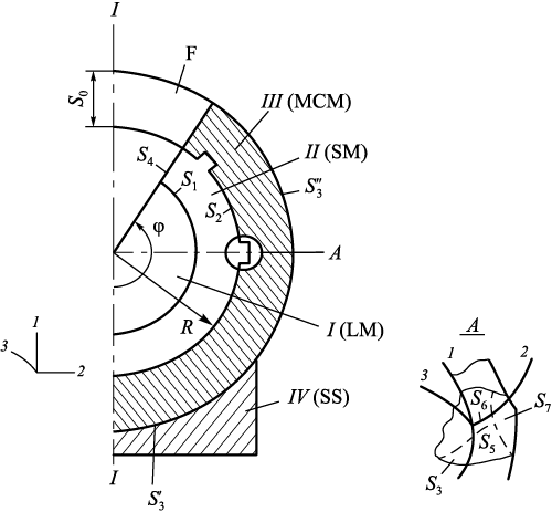
An axisymmetric body of revolution is considered (Fig. 1), consisting in meridional section of the following domains: I – liquid phase (steel); II – solid phase (solid metal); III – metal casting mold with annular recesses on its inner surface; IV – support structure (SS). The mold is a split-type design with inner annular recesses. Molten metal is poured into the mold cavity from the top through a funnel. View A presents a sketch of an annular recess on the inner surface of the mold, along with the corresponding surfaces where boundary conditions are applied.
Fig. 1. Calculation scheme of the system with indication |
The computational scheme presented below closely reflects the actual technological process used to produce spherical steel castings in a metal mold.
Since the problem is formulated as a Cauchy problem, the physical process of heat removal during cooling may be implemented by any known technological method, such as natural or forced cooling, etc.
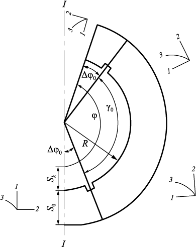
A configuration with two recesses on the inner surface of the mold is considered (Fig. 2). The objective is to determine an optimal arrangement of these recesses such that the maximum absolute values of the normal stresses σ22 are minimized.
Fig. 2. Scheme of the system I (LM) – II (SM) – III (MCM) |
The objective function for this condition is defined as:
| \[F = \min \left| {{\sigma _{22}}(\gamma )} \right|\max \left| {{\sigma _{22}}\left( {{{\left. Q \right|}_{{S_2}}},\tau } \right)} \right|\] | (1) |
with constrains
| \[\begin{array}{c}0 \le {\gamma _0} \le 120^\circ ;\\0 < \tau \le 15{\rm{ c}};\end{array}\] | (2) |
here, Q is the area of the meridional cross section of mold.
The constraint on τ is based on the solution to a similar problem, where, during the cooling of liquid metal in a mold without recesses, the magnitudes of the normal stresses σ22 , and σ33 in cross sections begin to decrease at τ > 10 с. The constraint on the recess opening angle γ0 arises from the condition that the reduction in compressive stress σ22 caused by the recess affects only a limited region.
The central part of the problem involves solving a system of equations from the linear theory of elasticity at a given time step \(\bar \Delta {\tau _n}\).
Using the equations of linear elasticity, we formulate for each domain the corresponding system of equations in Cartesian coordinates:
‒ domain I (liquid metal):
| \[\begin{array}{c}{\sigma _{11}} = {\sigma _{22}} = {\sigma _{33}} = \sigma = - {P_1};\\\dot \theta = {a_1}\Delta \theta ;\end{array}\] | (3) |
‒ domains II and III (solid metal and mold):
| \[\left\{ \begin{array}{l}{\sigma _{ij,j}} = 0,{\rm{ }}i;\\{\sigma _{ij}} - \sigma {\delta _{ij}} = 2{G_p}\varepsilon _{ij}^*;{\rm{ }}\varepsilon _{ij}^* = {\varepsilon _{ij}} - \frac{1}{3}\varepsilon {\delta _{ij}};\\\varepsilon = {\varepsilon _{ii}};\\{\varepsilon _{ii}} = 3{k_p}\sigma + 3{\alpha _p}\left( {\theta - \theta _p^*} \right);\\{\varepsilon _{ij}} = 0,5\left( {{U_{i,j}} + {U_{j,i}}} \right);\\\dot \theta = {a_p}\Delta \theta ,\end{array} \right.\] | (4) |
where Ui is displacements; εij is strain components; σ is hydrostatic stress; p = I, II, III – computational domains; Gp(θ) is shear modulus in domain p (p = II, III); Gp (p = II, III) – shear modulus for solid metal (p = II) and mold material (p = III); δij is Kronecker delta; kp is bulk compression coefficients; αp is coefficients of linear thermal expansion (p = II, III); ap is thermal diffusivity (p = I, II, III); θ is current temperature; τ is time; \(\theta _p^*\) is initial temperatures in domains p = I, II, III; P1 is pressure in the domain I; \({a_p} = \frac{{{\lambda _p}}}{{{c_p}{\gamma _p}}};\) λp is thermal conductivity; cp is specific heat capacity; γp is specific weight; Δ is Laplace operator.
During the cooling of the liquid metal, provided that θm ≤ θc (where θm is the metal temperature and θc is the crystallization temperature), the thickness of the solidified layer is determined from the phase transition solution:
| \[\frac{{d{\theta _1}}}{{dn}}{\lambda _1} - \frac{{d{\theta _2}}}{{dn}}{\lambda _2} = \frac{{dx}}{{d\tau }}L\rho ;\] | (5) |
where θ1 , θ2 are temperatures of the solid and liquid phases; λ1 , λ2 are thermal conductivities of the solid and liquid phases; L is latent heat of fusion; ρ is density of the solid phase; x is current thickness of the solidified metal layer; n is normal to the phase boundary.
Assuming that the temperature in the solid phase across the thickness δxn varies linearly, and the temperature gradient in the liquid phase is zero, the solution to equation (5) yields the following expression for determining the thickness of the solidified shell δxn at a given time step \(\bar \Delta {\tau _n}\) [21]:
| \[\delta {x_n} = C\sqrt \tau ;{\rm{ }}C = \sqrt {\frac{{2\bar \Delta {\theta _1}{\lambda _1}}}{{\rho L}}} ,\] | (6) |
where \(\bar \Delta {\theta _1}\) is the temperature drop in the solid phase near the crystallization front.
Initial conditions for problem (3), (4):
– \({\left. {\delta x} \right|_{\tau = 0}} = 0\) – no solid phase present in the metal;
– \({\left. {{\theta _1}} \right|_{\tau = 0}} = {\theta _0}\) – temperature of the poured liquid metal (1500 °С);
– \({\left. {\theta _3^*} \right|_{\tau = 0}} = {\theta ^*}\) – initial temperature of the mold (20 °С).
Initial stresses are assumed to be zero.
The system of equations (3), (4) is solved in an orthogonal coordinate system. The problem is axisymmetric, with the following symmetry conditions:
U3 = 0; σ31 = σ32 = 0; ε31 = ε32 = 0.
Boundary conditions for equations (3), (4) (see Fig. 1):
– on the axis of symmetry
U2 = 0; σ21 = 0; qhf = 0;
– on surfaces S1 – S8
| \[\begin{array}{c}{\left. {{\sigma _{11}}} \right|_{{S_1}}} = - {P_1};{\rm{ }}{\left. {{\sigma _{12}}} \right|_{{S_i}}} = 0{\rm{ }}(i = 1,{\rm{ }}5,{\rm{ }}6);\\{\left. {{\sigma _{11}}} \right|_{{{S''}_3}}} = 0;{\rm{ }}{\left. {{\sigma _{11}}} \right|_{{S_i}}} = 0{\rm{ }}(i = 5,{\rm{ }}6);\\{\left. {{\sigma _{12}}} \right|_{{S_3}}} = 0;{\rm{ }}{\left. {{\sigma _{22}}} \right|_{{S_i}}} = 0{\rm{ }}(i = 7,{\rm{ }}8);\\{\left. {{U_1}} \right|_{{{S'}_3}}} = 0;{\rm{ }}{\left. {{U_2}} \right|_{{S_4}}} = 0;{\rm{ }}{\left. {{\sigma _{21}}} \right|_{{S_i}}} = 0{\rm{ }}(i = 4,{\rm{ }}7,{\rm{ }}8);\\{\left. \theta \right|_{{S_1}}} = {\theta _0};{\rm{ }}{\left. \theta \right|_{{S_3}}} = {\theta ^*},\end{array}\] | (7) |
where qhf is heat flux; \({S_3} = {S'_3} + {S''_3}\) – surfaces where the mold is in contact with the support structure or exposed to the surrounding environment.
To solve the system of equations (3), (4) with boundary conditions (7), a numerical method was used, as described in [17] and previously applied in studies [21; 22]. The computational domain is divided by a system of orthogonal surfaces into finite-sized elements. For each element, the system (3), (4) is written in finite-difference form using the stress and displacement values on the element faces and the arc lengths of the edges forming the element. The resulting equations are solved using the initial and boundary conditions according to the algorithm and methodology developed in. The solution outputs include: stresses and displacements on the faces of each element; the average temperature of each element at the given time step. The numerical solution was implemented using a custom-developed program and the software package Odyssey2.
The finite-difference analogue of the heat conduction equation for an orthogonal element is constructed based on the principle of thermal balance [17]. It incorporates the average temperature within the element, the temperatures of the surrounding elements, and the arc lengths that define the orthogonal elements. The resulting system of equations is solved using a tridiagonal matrix algorithm (Thomas algorithm).
Solution algorithm
The solution of problem (1) with constraints (2) is carried out according to the following algorithm.
1. The computational domain is divided into a finite number of orthogonal elements; geometric dimensions S and R are specified.
2. The total cooling time τ* = 15 s in problem (1) with constraints (2) is divided into a finite number of time steps: τ* = \(\sum {\bar \Delta {\tau _n}} ,\) where n is the time step number.
3. The physical and mechanical properties of the materials are specified: liquid and solidifying steel, and the mold material.
4. The geometric parameters of the recesses are specified: \(\bar \Delta {\varphi _0}\), φ, γ0 .
5. The increment step for the current parameter γ is specified: \(\bar \Delta \gamma \).
6. Initial and boundary conditions are assigned to the elements that form the computational domain, including those forming the recesses.
7. Arc lengths of the elements within each domain are calculated.
8. The temperature field at the current time step \(\bar \Delta {\tau _n}\) is determined by solving the heat conduction equation using the initial and boundary conditions for that step.
9. If the temperature at surface S2 in domain I satisfies \({\left. \theta \right|_{{S_2}}}\) ≤ θc , the thickness of the solidified shell is calculated using equation (6); and the computational mesh is reconstructed starting from step 7. If \({\left. \theta \right|_{{S_2}}}\) > θc , proceed to step 10.
10. The system of equations (4) (excluding the heat conduction equations) is solved using the method described in [17]. The stress fields σij and displacement fields Ui (i, j = 1, 2, 3) are determined.
11. Across domain Q on surface S2 the maximum absolute value of the normal stress σ22 is identified and entered into matrix \({\left\{ {{\sigma _2}} \right\}^\prime }\).
12. A time step is performed. If \(\sum {\bar \Delta {\tau _n}} \) < τ*, return to step 8. If \(\sum {\bar \Delta {\tau _n}} \) = τ*, proceed to step 13.
13. From matrix \({\left\{ {{\sigma _2}} \right\}^\prime }\) the value σ22 = max\({\left\{ {{\sigma _2}} \right\}^\prime }\) is found and recorded in matrix \({\left\{ {{\sigma _2}} \right\}^{\prime \prime }}\).
14. The parameter is updated: γn = γn – 1 – \(\bar \Delta \gamma \); then τ = 0. If γn = 0, proceed to step 15, if γn > 0, return to step 6.
15. From matrix \({\left\{ {{\sigma _2}} \right\}^{\prime \prime }}\) the minimum value of \(\overline {{\sigma _{22}}} = \min {\left\{ {{\sigma _3}} \right\}^\prime }\) is selected along with the corresponding values of τ and γ.
16. End of the solution procedure.
Results and discussion
Geometric parameters of the mold: S0 = 50 mm, R = 20 mm, φ = 150°.
Time intervals (s): \({\bar \Delta {\tau _n}}\): 0.01; 0.02; 0.03; 0.04; 0.05; 0.1; 0.2; 0.3; 0.4; 0.5; 2.0; 5.0; 6.0; 8.0; 9.0; P1 = 1 kg/cm2.
Domain discretization: N1×N2 = 13×20.
According to the calculations, dividing the domain into 13×20 elements along the first and second coordinate axes for the mold without recesses is entirely suitable for the analysis performed. The same discretization (13×20 elements along the same coordinate axes) is equally justified for the mold with recesses.
Parameters of the poured steel for θ > 1000 °C (\(\theta _{\rm{m}}^*\) = 1000 °C):
G2 = 104 MPa; α1, 2 = 12·10–6 °С‒1; λ = 0.0298 W/(mm·°C); L1 = 270·103 J/kg (latent heat of fusion); C1, 2 = 444 J/(kg·°C); γ1 = 7.80·10–6 kg/mm3; θc = 1450 °C. | (8) |
The physical properties of the metal mold are the same as in equation (8), except that
\[{G_3} = 81{\rm{,}}000\left[ {1 - 1.2{{\left( {\frac{Q}{{1000}}} \right)}^2}} \right]{\rm{MPa}}{\rm{.}}\] | (9) |
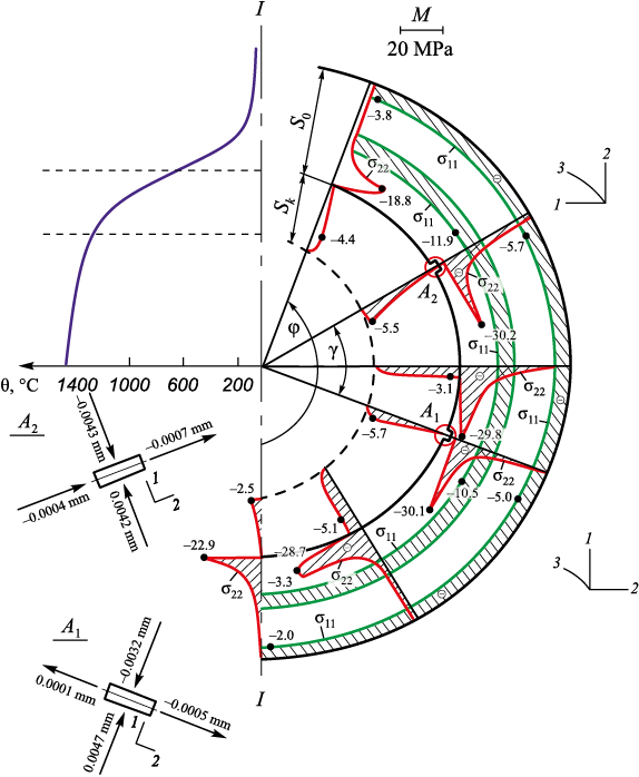
Initial values for the optimization process: \(\bar \Delta {\varphi _0}\) = 23°, γ0 = 104°; recess dimensions A1 , A2 (7.1×2.6) mm along axes 1 and 2 (Fig. 3). The recess dimensions correspond to the dimensions of the mesh elements.
Fig. 3. Plots of normal stresses σ11 , σ22 and displacements U1 , U2 |
As a result of the calculations performed using the above algorithm, the following parameters were obtained:
F = 29.8 MPa; γ = 60°; τ = 8.6 s. | (10) |
Fig. 3 presents the distributions of σ11 , σ22 and displacements U1 , U2 along the edges of recesses A1 and A2 in the mold. It can be seen that at the inner corners of recesses A1 and A2 there are stress concentrations for σ22 , with values of –30.1 MPa and –30.2 MPa, respectively. These values are slightly higher (in magnitude) than the value of F obtained above. For comparison, Fig. 4 shows the σ22 distribution (in MPa) across the section of a mold without recesses at the same time (τ = 8.6 s). The σ33 distribution is not shown, as it is approximately equal to σ22 , differing by no more than ±1 %.
Fig. 4. Plots of normal stresses σ22 along the mold section |
A pronounced difference in σ22 values is evident.
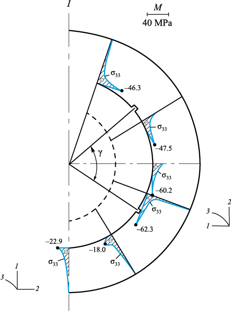
Fig. 5 shows the σ33 distribution for the parameters given in equation (10).
Fig. 5. Plots of normal stresses σ33 in the mold |
Although σ33 decreases (in magnitude) in many sections, a considerable portion of the mold still experiences high compressive stresses (more than 60 MPa). This indicates that optimization should be carried out for both σ22 and σ33. The σ22 stress was chosen for initial optimization because the recesses in the mold effectively cut through the regions of high S3 , at the early stage of cooling (Fig. 4), without disturbing axial symmetry. However, to achieve a more global reduction in compressive stresses σ22 and σ33 , it would likely be necessary to introduce additional recesses perpendicular to the existing ones.
This, however, represents a different, non-axisymmetric problem, requiring different equations and boundary conditions.
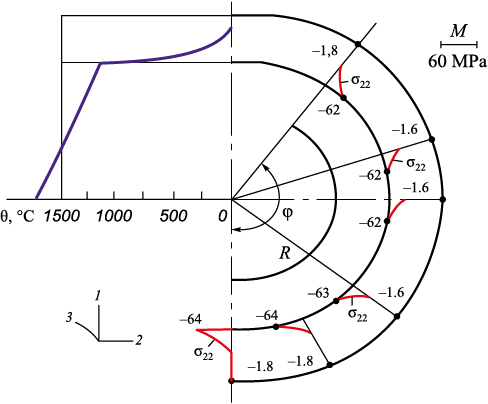
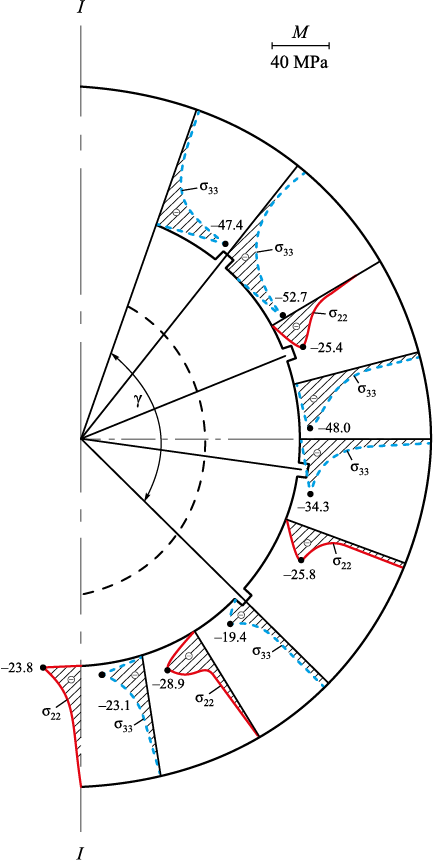
Within the present study, an attempt was made to reduce σ33 (in magnitude) by introducing additional recesses on surface S2 . According to equation (10), the recesses are arranged symmetrically on surface S2 at an angle φ, with an opening angle γ (Fig. 2). The highest σ33 values (in magnitude) occur within this opening angle γ (Fig. 5). Therefore, two additional recesses were placed on surface S2 within the previously determined opening angle γ. The SSS of the shell-type steel mold with four recesses on surface S2 was then calculated using the above algorithm for τ = 8.6 s. In this case, the algorithm was significantly simplified, as the recess configuration was fixed and the cooling time predetermined. Fig. 6 shows the σ22 and σ33 distributions across the mold section at the end of the time step τ* = 8.6 s. The results indicate a marked reduction (in magnitude) in both σ22 and σ33 stresses.
Fig. 6. Plots of calculated values of normal stresses |
In summary, the novelty of this work lies in formulating a problem aimed at determining the optimal arrangement of temperature seams as technologically significant areas, along with the corresponding stress values in a spherical metal mold, within the framework of a min–max objective function, as well as in developing a solution algorithm.
The proposed methodology, modeling algorithm, and optimization approach for enhancing the crack resistance of spherical metal molds can also be applied to numerical solutions of other problems involving various functional shells.
Conclusions
The problem of optimizing the design parameters of temperature seams in a spherical metal casting mold during the pouring of molten metal has been formulated and solved. The analysis of the SSS revealed structural features of the spherical metal casting mold design.
The presence of temperature seams on the surface in contact with the molten metal in the mold’s inner part significantly reduces the effect of thermal stresses that arise in the initial moments of casting cooling.
Rational regions for placing temperature seams in the meridional section of the mold and the corresponding stress values have been determined under the conditions of a min–max objective function, using the developed solution algorithm.
References
1. Evstigneev A.I., Dmitriev E.A., Odinokov V.I., Chernyshova D.V., Evstigneeva А.А., Ivankova E.P. On the crack resistance of a ceramic shell mold according to the smelted models when a spherical steel casting solidifies in it. Foundry. Technologies and Equipment. 2022;(9):17–21. (In Russ.).
2. Mikhailov A.M., Bauman B.V., Blagov B.N. B.N., etc. Foundry Production: Textbook for metallurgical specialties of universities. Moscow: Mashinostroenie; 1987:256. (In Russ.).
3. Golofaev A.N. Calculation of stress-strain state of coils by the finite element method. Foundry. Technologies and Equipment. 1983;(5):16. (In Russ.).
4. Dembovskii V.V. Numerical modeling of castings forming in metal molds. Foundry. Technologies and Equipment. 1992;(6):31–32. (In Russ.).
5. Ogorodnikova O.M. Stress-strain state of metal in the effective crystallization interval. Foundry. Technologies and Equipment. 2012;(9):21–24. (In Russ.).
6. Desnitskaya L.V., Desnitskii V.V., Matveev I.A. Consideration of the stress-strain state of crystallizing steel castings in their production technology. Foundry. Technologies and Equipment. 2019;(4):6–8. (In Russ.).
7. Gamer U. On the elastic-plastic deformation of a sphere subjected to As spherically symmetrical temperature field. Journal of Thermal Stresses. 1988;11(3):159–173. https://doi.org/10.1080/01495738808961930
8. Kholdi M., Loghman A., Ashrafi H., Arefi M. Analysis of thick-walled spherical shells subjected to external pressure: Elastoplastic and residual stress analysis. Proceedings of the Institution of Mechanical Engineers, Part L: Journal of Materials: Design and Applications. 2019;234(1):146442071988295. https://doi.org/10.1177/1464420719882958
9. Güven U. On stress distributions in functionally graded isotropic spheres subjected to internal pressure. Mechanics Research Communications. 2001;28(3):277–281. https://doi.org/10.1016/s0093-6413(01)00174-4
10. Ootao Y., Ishihara M. Transient thermoelastic analysis for a multilayered hollow cylinder with piecewise power law nonhomogeneity due to asymmetric surface heating. Acta Mechanica. 2014;225(10):2903–2922. https://doi.org/10.1007/s00707-014-1204-3
11. Saiyan S.G., Paushkin A.G. Development and verification of the two-layer thick-walled spherical shell’s finite element model under temperature and force exposure. IOP Conference Series: Materials Science and Engineering. 2020;913(3):032058. https://doi.org/10.1088/1757-899X/913/3/032058
12. Miller G.K. Stresses in a spherical pressure vessel undergoing creep and dimensional changes. International Journal of Solids and Structures. 1995;32(14):2077–2093. https://doi.org/10.1016/0020-7683(94)00197-5
13. Karami K., Abedi M., Zamani Nejad M., Lotfian M.H. Elastic analysis of heterogeneous thick-walled spherical pressure vessels with parabolic varying properties. Frontiers of Mechanical Engineering. 2012;7(4):433–438. https://doi.org/10.1007/s11465-012-0336-1
14. Abdelsalam O.R. Design optimization for a three-layers shrink-fitted pressure vessel exposed to very high pressure. IOP Conference Series: Materials Science and Engineering. 2019;610:012077. https://doi.org/10.1088/1757-899x/610/1/012077
15. Vitucci G., Mishuris G. Analysis of residual stresses in thermoelastic multilayer cylinders. Journal of the European Ceramic Society. 2016;36(9):2411–2417. https://doi.org/10.1016/j.jeurceramsoc.2015.12.003
16. Odinokov V.I., Dmitriev E.A., Evstigneev A.I., Namokonov A.N., Chernyshova D.V., Evstigneeva A.A. Modeling the stress-strain state and optimizing the angle of contact of a spherical shell mold by a support filler. Journal of Applied Mechanics and Technical Physics. 2025;(1):189–196. (In Russ.). https://doi.org/10.15372/PMTF202415455
17. Odinokov V.I., Kaplunov B.G., Peskov A.V., Bakov A.V. Mathematical Modeling of Complex Technological Processes. Moscow: Nauka; 2008:178. (In Russ.).
18. Alekseev G.V., Levin V.A., Tereshko D.A. Simulation and optimization in the problems of design of spherical layered thermal shells. Journal of Applied Mechanics and Technical Physics. 2019;60(2):323–331. https://doi.org/10.15372/PMTF20190213
19. Zhang Y.C., Jin C.W., Pang M. Plastic instability for a plastic orthotropic spherical pressure vessel under internal impulsive loading. Journal of Applied Mechanics and Technical Physics. 2022;63(2):343–346. (In Russ.). https://doi.org/10.1134/S0021894422020183
20. Alekseev G.V., Soboleva O.V., Tereshko D.A. Identification problems for a steady-state model of mass transfer. Journal of Applied Mechanics and Technical Physics. 2008; 49(4):537–547. https://doi.org/10.1007/s10808-008-0071-x
21. Evstigneev A.I., Dmitriev E.A., Chernyshova D.V., Odinokov V.I., Evstigneeva A.A., Ivankova E.P. Modeling of external force action on a shell mold for pouring steel. Matematicheskoe modelirovanie. 2022;34(5):61–72. (In Russ.). https://doi.org/10.20948/mm-2022-05-04
22. Evstigneev A.I, Odinokov V.I., Dmitriev E.A., Sviridov A.V., Ivankova E.P. The influence of external heat exposure on the stress state of shell forms by smelting models. Matematicheskoe modelirovanie. 2021;33(1):63–76. (In Russ.). https://doi.org/10.20948/mm-2021-01-05
About the Authors
A. I. EvstigneevRussian Federation
Aleksei I. Evstigneev, Dr. Sci. (Eng.), Prof., Chief Researcher of the Department of Research Activities
27 Lenina Ave., Komsomolsk-on-Amur, Khabarovsk Territory 681013, Russian Federation
D. V. Chernyshova
Russian Federation
Dar’ya V. Chernyshova, Postgraduate of the Chair of Aircraft Engineering
27 Lenina Ave., Komsomolsk-on-Amur, Khabarovsk Territory 681013, Russian Federation
V. I. Odinokov
Russian Federation
Valerii I. Odinokov, Dr. Sci. (Eng.), Prof., Chief Researcher of the Department of Research Activities
27 Lenina Ave., Komsomolsk-on-Amur, Khabarovsk Territory 681013, Russian Federation
E. A. Dmitriev
Russian Federation
Eduard A. Dmitriev, Dr. Sci. (Eng.), Assist. Prof., Rector
27 Lenina Ave., Komsomolsk-on-Amur, Khabarovsk Territory 681013, Russian Federation
A. A. Evstigneeva
Russian Federation
Anna A. Evstigneeva, MA Student of the Chair “Applied Mathematics”
27 Lenina Ave., Komsomolsk-on-Amur, Khabarovsk Territory 681013, Russian Federation
Yu. B. Koloshenko
Russian Federation
Yuliya B. Koloshenko, Senior Lecturer of the Chair of Aircraft Engineering
27 Lenina Ave., Komsomolsk-on-Amur, Khabarovsk Territory 681013, Russian Federation
D. A. Potyanikhin
Russian Federation
Dmitrii A. Potyanikhin, Cand. Sci. (Phys.-Math.), Assist. Prof. of the Chair of Aircraft Engineering
27 Lenina Ave., Komsomolsk-on-Amur, Khabarovsk Territory 681013, Russian Federation
Review
For citations:
Evstigneev A.I., Chernyshova D.V., Odinokov V.I., Dmitriev E.A., Evstigneeva A.A., Koloshenko Yu.B., Potyanikhin D.A. Modeling and optimization of the effect of temperature seams on stress-strain state of spherical metal casting molds. Izvestiya. Ferrous Metallurgy. 2025;68(4):372-382. https://doi.org/10.17073/0368-0797-2025-4-372-382


