Scroll to:
Calculation of temperature and thermoelastic stresses in strikers during production of hollow steel billets in a unit of combined casting and deformation. Part 1
https://doi.org/10.17073/0368-0797-2025-4-366-371
Abstract
The article solves the problem of determining the temperature of calibrated strikers in a unit of combined casting and deformation during production of hollow steel billets. The authors substantiate the relevance of determining temperature fields and thermoelastic stresses in calibrated strikers when compressing the wall of a hollow billet and at full speed when cooling the strikers with water, and describe the strength and thermophysical properties of the steel from which the strikers are made. Geometry of the striker for producing a hollow billet in one pass is shown. The paper considers the initial data and temperature boundary conditions for calculating the temperature field of the striker during production of hollow billets in a unit of combined casting and deformation. The boundary conditions are given to determine the striker temperature as well as the values of heat flow and effective heat transfer coefficient. The results of calculating the temperature fields are performed in four sections and are presented for characteristic lines and points located on the striker contact surface and in the contact layer at a depth of 5 mm from the working surface. Dimensions of the finite element grid were used in calculating the temperature field of the strikers. The temperature field of the strikers with collars was determined based on solution of the unsteady thermal conductivity equation with the corresponding initial and boundary conditions. The values and patterns of temperature distribution in a calibrated striker are presented when the wall of a hollow billet is compressed and when a hollow billet is produced in one pass in a unit of combined casting and deformation.
Keywords
For citations:
Lekhov O.S., Bilalov D.Kh. Calculation of temperature and thermoelastic stresses in strikers during production of hollow steel billets in a unit of combined casting and deformation. Part 1. Izvestiya. Ferrous Metallurgy. 2025;68(4):366-371. https://doi.org/10.17073/0368-0797-2025-4-366-371
Introduction
The technology for producing hollow steel billets at pipe plants entails high capital, energy, and operating costs, since it includes casting solid round billets on horizontal continuous casting machines, heating them in furnaces, and piercing on presses or piercing rolling mills. Note that this equipment is predominantly of foreign manufacture, and under anti-Russian sanctions its supply may be halted. Accordingly, a domestic unit of combined casting and deformation has been developed that successfully replaces foreign equipment and can produce hollow steel billets in one pass [1 ‒ 3]. The most heavily loaded elements of the unit during hollow-billet production are calibrated strikers, which, during the working stroke, simultaneously compress the wall of the hollow billet and draw it out of the mold. In this case, calibrated strikers experience combined stresses from the compression force and the temperature load, which reduce the service life of the strikers. To select the design parameters and material of the calibrated strikers on a sound basis, it is necessary to determine their stress state during the production of hollow billets on the unit of combined casting and deformation. To this end, the temperature field and thermoelastic stresses in the strikers during compression of the wall of the hollow billet must be determined [4 ‒ 6].
This paper presents a procedure for calculating temperature fields and thermoelastic stresses in the strikers of a unit of combined casting and deformation. The pipe billet material is steel grade 09G2S; the inner and outer diameters of the pipe billet are 60 and 100 mm, respectively. The angular speed of the eccentric shafts is 40 rpm. At this speed, the striker contact time in the working stroke is 0.375 s, and the pause time is 0.375·3 = 1.125 s. The temperature of the pipe billet at the entry to the striker is 1200 °C, and after exiting the strikers it is 1000 °С.
The striker material is forged tool steel 4Kh4VMFS. For calculations for this steel in the temperature range from 20 to 700 °C, the following were adopted: modulus of elasticity E, density ρ, thermal conductivity λ, heat capacity c, coefficient of linear expansion α, and yield strength σy [2].
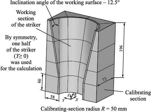
The geometry of the striker with dimensions is shown in Fig. 1.
Fig. 1. Geometry of the striker with dimensions |
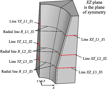
By symmetry, the calculation was performed for one half of the striker (Fig. 2). A part of visible lines is shown, for which calculation results will be presented below.
Fig. 2. Geometry of one half of the striker (part of the visible lines) |
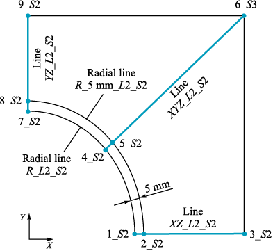
The results of the temperature and stress calculations are given for three sections (1, 2 and 3), in each section, results are presented for five lines. The positions of the sections, the lines for each section, and the points through which the lines pass are shown in Fig. 3. Table 1 lists the names of all the lines and indicates the points through which these lines pass.
Fig. 3. Position of points and lines in section 2
Table 1. Names of the lines for three sections, the points
| ||||||||||||||||||||||||||||||||||||||||||
Calculations of the thermal and stress states of the strikers – for each thermal load (temperature boundary conditions), the specified thermo-physical and mechanical properties of the striker material, and the striker geometry – were performed as follows:
1. Using the thermal element SOLID 70, with the given temperature boundary conditions and thermophysical parameters (density, thermal conductivity, heat capacity) of the striker material, a quasi-steady-state (QSS) temperature field of the striker at the end of the working stroke and at the end of the pause [7 ‒ 9].
2. Using the structural element SOLID 185, together with the modulus of elasticity and Poisson’s ratio and the temperature field at the end of the working stroke (from step 1), the thermal stress state of the striker at the end of the working stroke was determined along the striker length [10 ‒ 12].
The temperature field of the strikers is found by solving the unsteady thermal conductivity equation with the corresponding initial and temperature boundary conditions in the ANSYS package [10]:
| \[c{\rm{\rho }}\frac{{dT}}{{dt}} = \sum\limits_{i = 1}^3 {\frac{\partial }{{\partial {x_i}}}} \left( {\lambda \frac{{\partial T}}{{\partial {x_i}}}} \right),\] | (1) |
All coefficients are taken as temperature-dependent for the strikers.
The initial condition for T(\(\vec X\), t) is:
| \[T(\vec X,{\rm{ }}t) = {T_0}(\vec X).\] | (2) |
The initial temperature of the strikers is 20 °С.
For the working surface of the striker, boundary conditions of the second kind have the form
| \[{\left. {{\rm{\lambda }}\frac{{\partial T}}{{\partial n}}} \right|_S}(t) = q,\] | (3) |
where q is the density of heat flow from the metal in the deformation zone.
During the pause, the boundary conditions of the third kind for the working surface have the form
| \[\lambda \frac{{\partial T}}{{\partial n}} = - {\alpha _1}(T - {T_{\rm{k}}}),\] | (4) |
where α1 is the effective heat transfer coefficient on the working surface during the pause; Тk = 60 °С is the temperature of the water supplied to the working surface of the strikers during the pause.
On the striker end face, the back wall, and the top and bottom of the striker, the boundary conditions of the third kind have the form
| \[\lambda \frac{{\partial T}}{{\partial n}} = - {\alpha _2}(T - {T_{\rm{a}}}),\] | (5) |
where α2 is the heat transfer coefficient for cooling the back wall and the top and bottom with water or air, depending on the calculation case; Тa = 60 °С is the ambient temperature at the end face, back wall, and top and bottom.
In this formulation, one assumption is that the radiative heat flow from the metal is neglected in calculating the striker temperature fields [13 ‒ 15].
Equations (1) – (5) constitute an initial boundary-value problem for the unsteady temperature field of the strikers in the unit of combined casting and deformation [16 ‒ 18].
This scheme for determining temperature and thermoelastic stresses in the strikers by the finite element method is implemented in one of the modules of the ANSYS package [19; 20].
Temperature values at all points along the lines are given in Table 2.
Table 2. Temperature values at all points of the lines |
| Section 1 | Section 2 | Section 3 | ||||||
| Point | Temperature, °С | Point | Temperature, °С | Point | Temperature, °С | |||
| WC | HF | WC | HF | WC | HF | |||
| 1_S1 | 370 | 451 | 1_S2 | 365 | 445 | 1_S3 | 354 | 435 |
| 2_S1 | 392 | 392 | 2_S2 | 386 | 386 | 2_S3 | 373 | 373 |
| 3_S1 | 370 | 370 | 3_S2 | 350 | 350 | 3_S3 | 310 | 310 |
| 4_S1 | 368 | 448 | 4_S2 | 360 | 441 | 4_S3 | 348 | 429 |
| 5_S1 | 389 | 389 | 5_S2 | 381 | 381 | 5_S3 | 366 | 366 |
| 6_S1 | 344 | 344 | 6_S2 | 330 | 330 | 6_S3 | 285 | 285 |
| 7_S1 | 304 | 385 | 7_S2 | 294 | 375 | 7_S3 | 289 | 370 |
| 8_S1 | 314 | 314 | 8_S2 | 302 | 302 | 8_S3 | 295 | 295 |
| 9_S1 | 286 | 286 | 9_S2 | 252 | 252 | 9_S3 | 221 | 221 |
| N o t e. WC and HF denote the temperature at the end of the pause and at the end of the working stroke (end of contact), respectively. | ||||||||
Analysis of calculation results
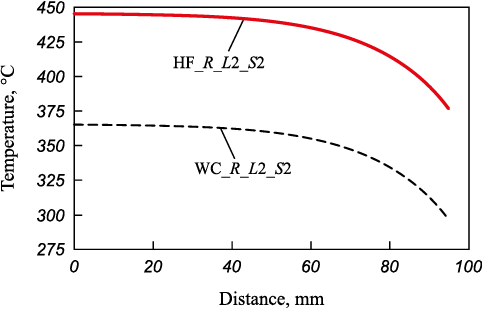
Under heat flow during wall reduction, the contact surface of the striker reaches 370 – 451 °C (results shown only for the portion between sections 1 – 3; Table 1, points 7_S3 and 1_S1). The maximum temperature occurs in section 1 on the plane of symmetry of the striker. During idle operation with water cooling, the contact-surface temperature decreases to 289 – 370 °C (points 7_S3 and 1_S1) while the maximum remains in section 1 on the plane of symmetry.
At a depth of 5 mm, the temperatures at the end of contact and at the end of the pause in the QSS mode coincide and depend only on location; they lie within 295 ‒ 392 °С (points 8_S3 and 2_S1). The maximum is again in section 1 on the plane of symmetry.
Temperature variation is similar through the thickness and along the radius. The maximum temperature – at the end of contact and at the end of the pause – at the working surface of the striker and at a depth of 5 mm occurs in the part of the striker located closer to the mold; toward the calibrating section the temperature decreases. Radially, the temperature is highest on the plane of symmetry and decreases toward the lateral surface of the striker.
Through the thickness, the striker temperature decreases: on the support side surface it is 285 ‒ 370 °С (points 6_S3 and 3_S1); on the lateral surface side it is 221 – 286 °C (points 9_S3 and 9_S1).
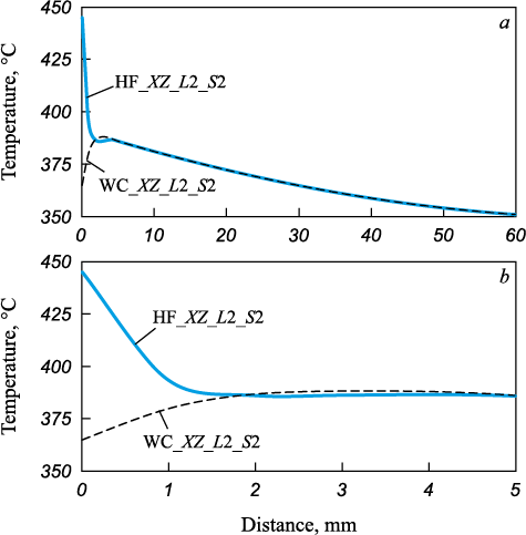
Temperature equalization occurs at a depth of 2 mm from the contact surface, both through the thickness and along the radius.
Figs. 4 and 5 show the temperature distribution along characteristic lines of the calibrated striker in section 2 during wall reduction and during idle operation with water cooling. Temperatures at characteristic points in sections 1 and 2 differ only slightly (Table 2).
Fig. 4. Nature of temperatures along the XZ_L2_S2 line due
Fig. 5. Nature of temperatures along the R_L2_S2 line due to the effect |
Conclusions
A procedure has been developed for calculating temperature fields and thermoelastic stresses in calibrated strikers of a unit of combined casting and deformation during the production of steel pipe billets. The temperature distribution along characteristic lines has been determined for both wall reduction and idle operation with water cooling. It has been established that, under heat flow during wall reduction, the temperature of the contact surface of the striker is 370 – 451 °С.
References
1. Lekhov O.S., Mikhalev A.V. Unit of Combined Continuous Casting and Deformation for Production of Steel Sheets for Welded Pipes. Theory and Calculation. Yekaterinburg: UPI; 2017:151. (In Russ.).
2. Lekhov O.S., Mikhalev A.V., Shevelev M.M. Stresses in the Striker–Strip System during Production of Steel Sheets at a Unit of Continuous Casting and Deformation. Yekaterinburg: UPI; 2018:125. (In Russ.).
3. Lekhov O.S., Bilalov D.Kh. Technological capabilities of installations for combined continuous casting and deformation processes for the production of metal products. Proizvodstvo prokata. 2016;(7):24–26. (In Russ.).
4. Khloponin V.N., Kosyreva M.V., Kosyak A.S. Influence of cooling system on thermal operating conditions of roll surface layer. In: Proceedings of the MISIS. Issue 100. Moscow: MISiS; 1977:90–93. (In Russ.).
5. Boley B.A., Weiner J.H. Theory of Thermal Stresses. New York: John Wiley & Sons; 1960:586.
6. Lekhov O.S. Study of stress-strain state of rolls-band system at rolling of broad-flanged beam in stands of universal beam mill. Report 2. Izvestiya. Ferrous Metallurgy. 2014;57(12):15–19. (In Russ.). https://doi.org/10.17073/0368-0797-2014-12-15-19
7. Kushner V.S., Vereshchaka A.S., Skhirtladze A.G., Negrov D.A. Technological Processes in Mechanical Engineering. Part II. Metal Forming and Welding Production. Omsk: OmSTU; 2005:200. (In Russ.).
8. Bulanov L.V., Karlinskii S.E., Volegova V.E. Durability of casters for external and internal cooling. In: Reliability of Large Machines. Collection of Sci. Papers. NIItyazhmash. Sverdlovsk: NIItyazhmash; 1990:126–132. (In Russ.).
9. Lykov A.V. Theory of Thermal Conductivity. Moscow: Vysshaya shkola; 1967:600. (In Russ.).
10. ANSYS. Structural Analysis Guide. Rel. 15.0.
11. Matsumia Т., Nakamura Y. Mathematical model of slab bulging during continuous casting. In: Applied Mathematical, and Physical Models in Iron and Steel Industry: Proceedings of the 3rd Process. Tech. Conf., Pittsburgh, Pa, 28-31 March 1982. New York; 1982:264–270.
12. Takashima Y., Yanagimoto I. Finite element analysis of flange spread behavior in H-beam universal rolling. Steel Research International. 2011;82(10):1240–1247. https://doi.org/10.1002/srin.201100078
13. Kobayashi S., Oh S.-I., Altan T. Metal Forming and Finite-Element Method. New York: Oxford University Press; 1989:377.
14. Karrech A., Seibi A. Analytical model of the expansion in of tubes under tension. Journal of Materials Processing Technology. 2010;210:336–362.
15. Kazakov A.L., Spevak L.F. Numeral and analytical studies of nonlinear parabolic equation with boundary conditions of a special form. Applied Mathematical Modelling. 2013; 37(10-13):6918–6928. https://doi.org/10.1016/j.apm.2013.02.026
16. Jansson N. Optimized sparse matrix assembly in finite element solvers with one-sided communication. In: High Performance Computing for Computational Science – VECPAR 2012. Berlin, Heidelberg: Springer; 2013:128–139.
17. Park C.Y., Yang D.Y. A study of void crushing in large forgings II. Estimation of bonding efficiency by finite-element analysis. Journal of Materials Processing Technology. 1997;72(1):32-41.
18. Sorimachi K., Emi T. Elastoplastic stress analysis of bulging as a major cause of internal cracks in continuously cast slabs. Tetsu-to-Hagane. 1977;63(8):1297–1304. https://doi.org/10.2355/tetsutohagane1955.63.8_1297
19. Marciniak Z., Duncan J.L., Hu S.J. Mechanics of Sheet Metal Forming. Oxford: Butterworth-Heinemann Elsevier Ltd.; 2002:228.
20. Fujii H., Ohashi T., Hiromoto T. On the formation of the internal cracks in continuously cast slabs. Tetsu-to-Hagane. 1978;18(8): 510–518. https://doi.org/10.2355/tetsutohagane1955.62.14_1813
About the Authors
O. S. LekhovRussian Federation
Oleg S. Lekhov, Dr. Sci. (Eng.), Prof. of the Chair of Engineering and Vocational Training in Machinery and Metallurgy
11 Mashinostroitelei Str., Yekaterinburg 620012, Russian Federation
D. Kh. Bilalov
Russian Federation
Damir Kh. Bilalov, Assist. Prof. of the Chair of Engineering and Vocational Training in Machinery and Metallurgy
11 Mashinostroitelei Str., Yekaterinburg 620012, Russian Federation
Review
For citations:
Lekhov O.S., Bilalov D.Kh. Calculation of temperature and thermoelastic stresses in strikers during production of hollow steel billets in a unit of combined casting and deformation. Part 1. Izvestiya. Ferrous Metallurgy. 2025;68(4):366-371. https://doi.org/10.17073/0368-0797-2025-4-366-371


