Scroll to:
Methodology for calculating the flatness of cold-rolled steel strips
https://doi.org/10.17073/0368-0797-2025-4-417-423
Abstract
A known cause of flat shape defects in finished cold-rolled steel strips is the inequality of the drawing ratios across the strip width. Difference in the values of these ratios is affected by the roll barrel profiling parameters, energy-power parameters of rolling, operating parameters of the automatic profile and strip shape control system. The impact of all technological factors on the strip shape is complex. The paper considers an approach that takes into account the main operating parameters of rolling equipment allowing to estimate the type and amplitude of flatness defects in finished steel strips. When implementing this approach, 6 calculation stages were performed: energy-power calculation of the cold rolling process; calculation of elastic deformations of the working roll barrel surface; assessment of wear of the working roll barrel surface; calculation of the roll thermal profile; assessment of convexity of the steel strip transverse profile; assessment of flatness indicators of the finished strip. To calculate the parameters affecting the flatness of the rolled product, known calculation methods adapted to specific process conditions were used. The results of assessing the shape indicators of the rolled strip obtained using the model were compared with the results of modeling in the Deform 3D program. The modeling results demonstrated reliability of the proposed approach to assessing the rolled product quality.
Keywords
For citations:
Shalaevskii D.L. Methodology for calculating the flatness of cold-rolled steel strips. Izvestiya. Ferrous Metallurgy. 2025;68(4):417-423. https://doi.org/10.17073/0368-0797-2025-4-417-423
Introduction
The primary causes of flatness defects in cold-rolled steel strips are non-uniform deformation across the strip width and low sectional stiffness. The latter is a characteristic feature of flat-rolled products.
Most established studies consider the variation in drawing ratios across the strip width as the main criterion for flatness loss. Among the influencing factors, some are viewed as more critical than others [1 – 18].
Studies [2 – 4] propose flatness criteria based solely on drawing ratio values across the strip width. The research findings reported in [5 – 8] highlight the potential to assess flatness defects through cross-sectional characteristics of the strip.
Models that incorporate multiple technological parameters for evaluating strip flatness are presented in [9 – 11].
Approaches focusing on transverse profile characteristics for identifying flat shape defects are described in [12 – 14].
Further models, found in [15 – 18], attribute flatness loss to post-rolling strip cooling processes.
The flatness evaluation method outlined in [9] enables the calculation of defect amplitudes based on rolling process parameters. This method accounts for nearly all relevant factors, including roll barrel profiling, potential work roll wear, roll axis misalignment, and several other significant influences.
The aim of this study was to develop a method for evaluating the amplitude of waviness and buckling in cold-rolled strips based on the variation in drawing ratios across the width, and to validate it by comparing calculated results with those generated using the DEFORM-3D simulation software.
Problem statement and research methods
Calculating the amplitude of waviness or buckling in cold-rolled steel strips, based on the variation in drawing ratios across the strip width, requires comprehensive input data. This includes the elastic deformations of the work and backup rolls, the wear of their barrel surfaces, and the non-uniform thermal expansion across the width of the rolled strip.
Study [19] presents a regression-based model describing the elastic deformation of a four-high (“quarto”) mill stand along the work roll barrel. This relationship was derived through numerical simulation of elastic deformations in the roll system and was previously applied to model flatness formation in hot-rolled strips produced on a continuous wide-strip mill. It is also applicable to the integrated method proposed in the present study.
Additional research [20 – 22] offers methods for evaluating barrel surface wear and non-uniform thermal expansion along the roll barrel.
The type and amplitude of flatness defects in cold-rolled strips can be assessed using the methodology described in [23].
The reliability of the calculated results can be verified by evaluating strip shape quality indicators using the DEFORM-3D simulation software.
Results and discussion
The procedure for calculating the type and amplitude of flatness defects in cold-rolled steel strips included the following stages:
– Stage 1: calculation of the energy–power parameters of the cold rolling process;
– Stage 2: analysis of elastic deformation of the work roll barrel surface;
– Stage 3: assessment of wear on the work roll barrel surface;
– Stage 4: calculation of the roll thermal profile;
– Stage 5: evaluation of the convexity of the strip’s transverse profile;
– Stage 6: assessment of flatness parameters of the finished strip.
The first stage was implemented using a model of energy–power parameters that takes into account elastic deformation zones along the deformation zone length [24 – 25].
The second stage involved modeling elastic deformations of the four-high (quarto) mill roll system using a numerical simulation tool for analyzing process mechanics.
To determine the deformation of the work roll barrel surface, taking into account elastic flattening in the contact zones with the backup roll barrel and the strip during rolling, three-dimensional computational models were developed for the work and backup roll sets of a five-stand 1700 mm continuous cold rolling mill.
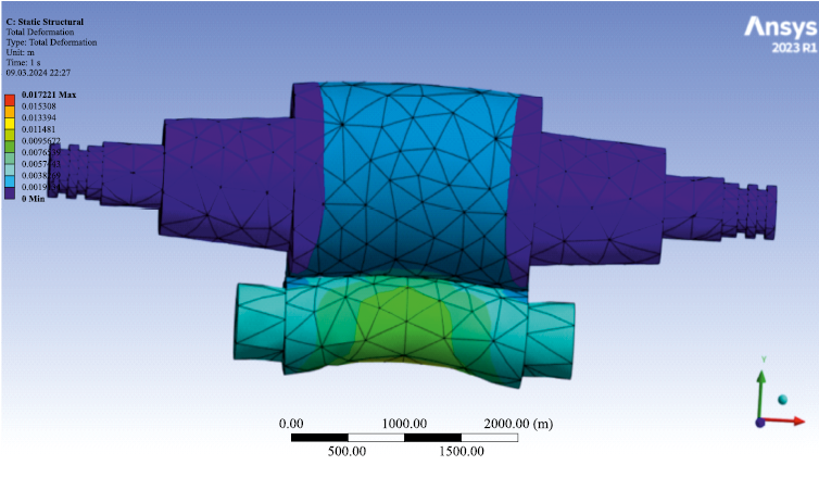
The roll set was imported into the MechanicalStructure module of ANSYS R1 (Fig. 1).
Fig. 1. Model of the roll system of “quarto” stand |
In the module’s pre-processor, a mesh was generated (Fig. 1). In ANSYS Workbench, high-carbon steel with a yield strength of 900 MPa was assigned as the roll material. To simulate support conditions, boundary constraints were applied to the backup roll necks along the X, Y, and Z axes (vertical direction), and to the work roll necks along the X and Y axes. In the vertical direction, the work roll rested on the backup roll barrel.
During the creation of the solid model, a specific region was defined on the surface of the work roll barrel to represent the deformation zone, where contact pressure would be applied. In this region, a pressure load equivalent to the normal stress in the deformation zone was assigned. To enable this setup, the Static Structure solver was launched in advance.
To simulate anti-bending force, concentrated vertical loads were applied to the ends of the work roll necks along the Y-axis.
During the simulation, the following parameters were varied within defined ranges: the contouring of the work and backup roll barrels, contact pressure in the deformation zone, strip width, and the anti-bending force applied to the work rolls.
A contour plot illustrating the results of elastic deformation calculations is presented in Fig. 2.
Fig. 2. Example of the result of calculating elastic deformations in vertical axial plane of the rolls |
The difference in elastic deformation of the work roll barrel surface between the strip edge and center (elastic deflection across the strip width) was generalized into the following regression equation
| Δdc – Δdedg = 0.00001632·10–5b + 0.007703P – – 0.00000305Pbend – 0.0200ΔDg.c. – 0.0169ΔDg.c.b , | (1) |
where P is the rolling force in the i-th stand, MN; Pbend is the anti-bending force applied to the work rolls, kN; b is the strip width, mm; ΔDg.c. is the ground crown of the work roll barrel at its center, mm; ΔDg.c.b is the ground crown of the backup roll barrel at its center, mm.
The coefficient of multiple determination R2 was 0.86, indicating a high degree of reliability for the derived equation.
The statistical significance of the coefficients in Equation (1) was assessed using p-values, based on a dataset of forty simulation variants previously reported in [19]. The results of this evaluation are presented in Table 1.
Table 1. Results of checking the significance of coefficients
| ||||||||||||||
The third stage – evaluation of wear on the work roll barrel surface – was based on experimental data that included roll operating parameters, surface hardness, and barrel contour geometry [20].
As shown in Table 2, roll wear is influenced by the rolling force, surface hardness of the roll barrel, barrel diameter, and the total length of strip rolled. Initial concavity was found to have a negligible effect.
Table 2. Results of assessing the Pearson correlation coefficients of the rolls parameters
|
A relationship was established to estimate roll barrel wear at both the center and strip edges, depending on the influencing parameters:
| Δc = kw P + kL Lm , | (2) |
where P is the average rolling force in the working stand since the installation of the work roll, MN; Lm is the total length of strip rolled on the work rolls in stand, m; kw is the coefficient representing the influence of rolling force on the wear of the work roll barrel surface; kL is the coefficient representing the influence of the strip length rolled on the work rolls in the stand on roll barrel wear.
The values of these coefficients, for example at the center of the roll barrel (i.e., along the strip centerline), were determined using the following regression equations
| kw = –0.00025HSD + 0.0000285D, | (3) |
where HSD is the Shore hardness of the roll barrel surface, D is the diameter of the work roll barrel, mm. The coefficient of determination for this equation is R2 = 0.89, indicating a high degree of reliability;
| kL = –0.0000011HSD + 0.00000011D. | (4) |
The forth stage was the calculation of the roll thermal profile.
The thermal behavior of the continuous cold rolling mill was analyzed by formulating and solving a system of heat balance equations for the work rolls, backup rolls, and strip. The application of this model for both cold and hot continuous strip rolling has been discussed in prior studies [21; 22].
The thermal crown of the roll barrel across the strip width was calculated using the temperature distribution determined from the system of equations, with particular focus on the roll barrel center.
The fifth stage involved assessing the strip’s profile using the components obtained in previous stages, which define the cross-sectional shape of the flat-rolled product at the roll gap exit:
– initial ground crown, adjusted for current wear, Δgy ;
– elastic deformation of the work roll barrel surface, Δdy ;
– thermal profile (thermal crown) of the roll barrel surface, Δty ;
– nominal strip thickness, hi .
The strip thickness at any point along the width (coordinate y) was calculated as:
| Δiy = hi – Δgy + Δdy – Δty . |
The six stage – evaluation of flatness parameters of the finished strip – was performed using the relationships described in [23].
By knowing the initial slab and final strip thickness profiles across the width – and thus the drawing ratios at the edges and center of the strip – it is possible to estimate the most important flatness defect parameter defined in GOST 19903–2015 – the defect amplitude:
– for “waviness” formed in the i-th stand of a continuous group of stands:
| \[{a_{{\rm{w}}i}} = \frac{{hE\left[ {1 - \cos \left( {\frac{{2{{\rm{\sigma }}_{\rm{k}}}\left( {{{\rm{\lambda }}_{{\rm{cr}}}} - {{\rm{\lambda }}_{\rm{c}}}} \right)}}{{hE}}} \right)} \right]}}{{{{\rm{\sigma }}_{\rm{k}}}}},\] | (5) |
where h is the strip thickness, E is the strip’s Young’s modulus, σk is the critical buckling stress, λcr , λc are the drawing ratios at the strip edge and center, respectively, based on the entry and exit cross-sections;
– “buckling” formed in the i-th stand of the continuous rolling mill:
| \[{a_{{\rm{b}}i}} = \frac{{hE\left[ {1 - \cos \left( {\frac{{2{{\rm{\sigma }}_{\rm{k}}}\left( {{{\rm{\lambda }}_{\rm{c}}} - {{\rm{\lambda }}_{{\rm{cr}}}}} \right)}}{{hE}}} \right)} \right]}}{{{{\rm{\sigma }}_{\rm{k}}}}}.\] | (6) |
It has been confirmed [23] that flatness defects accumulate as the strip passes from stand to stand. Therefore, if the same type of defect occurs in subsequent stands, its amplitude increases additively.
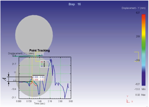
The accuracy of the calculated amplitude and type of waviness using Equations (5) and (6) was validated by simulating the rolling process in DEFORM-3D. For this purpose, roll barrel models were created with longitudinal profiles incorporating both elastic deformation and thermal crown across the strip width. Non-uniform roll barrel wear could also be taken into account. An entry slab was modeled with a specified cross-sectional profile, and the rolling process was simulated. In the post-processor, vertical displacement differences between the strip center and edges were tracked across the width.
In Fig. 3, Line 3 represents the vertical displacement at the strip edge, while Line 1 represents displacement at the center. The difference between them was taken as the defect amplitude.
Fig. 3. Example of assessing flatness defect of the “wave” strip |
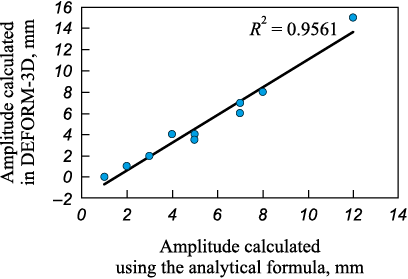
An example of amplitude evaluation using DEFORM-3D is shown in Fig. 4.
Fig. 4. Comparison of the results of calculating the non-flatness amplitude |
The validation results obtained from DEFORM-3D simulations confirm the sufficient accuracy of the analytical model for predicting the flatness of cold-rolled steel.
Conclusions
A well-known cause of flatness defects in finished cold-rolled steel strips is the variation in drawing ratios across the strip width. This variation is influenced by the roll barrel contouring parameters, the energy–power parameters of the rolling process, and the operating parameters of the automatic profile and flatness control system. The combined effect of these technological factors on strip shape is complex. This paper presents an approach that incorporates the key operational parameters of rolling equipment and enables the evaluation of the type and amplitude of flatness defects in finished steel strips.
References
1. Shalaevskii D.L. Models for the formation of flatness defects of steel strip during its rolling and heat treatment. Russian Metallurgy (Metally). 2024;2024(7):1760–1764. https://doi.org/10.1134/S0036029524703063
2. Budakva A.A., Konovalov Yu.V., Tkalich K.N. Roll Profiling for Sheet Metal Mills. Kiev: Tekhnika; 1986:190. (In Russ.).
3. Maksimov E.A., Shatalov R.L., Boskhamdzhiev N.Sh. Production of Flat Strips by Rolling. Moscow: Teplotekhnik; 2008:355. (In Russ.).
4. Shatalov R.L., Maksimov E.A., Verkhov E.Yu. Rational modes of control of strip flatness in thin-sheet reversible rolling. In: Scientific and Technical Progress in Ferrous Metallurgy: Proceedings of the II Int. Sci. and Tech. Conf. (October 7–9, 2015). Cherepovets: Cherepovetskii gos. un-t; 2015:148–151. (In Russ.).
5. Shatalov R.L., Maksimov E.A. Clarification of the method for calculating critical stresses and flatness indices of strip during thin-sheet rolling. Stal'. 2016;(4):26–30. (In Russ.).
6. Ievlev N.G. Mathematical models of flatness of thick sheet metal applied to automated process control systems. Matematichní mashini í sistemi. 2018;(1):67– 77. (In Russ.).
7. Shatalov R.L., Maksimov E.A. Analysis of asymmetric rolling efficiency for increasing accuracy of rolled strips. Metallurg. 2016;(7):80–84. (In Russ.).
8. Bartkhol’dt Kh., Kopin F., Dzhelali M. Universal flatness model for process optimization in cold rolling mills. Chernye metally. 2015;(3):53–58. (In Russ.).
9. Shalaevskii D.L., Mitrofanov A.V., Korepina K.P. Improvement in the flatness of finished steel strips under energy saving regimes of continuous hot rolling. Stal’. 2022;(2): 15–17. (In Russ.).
10. Garber E.A., Shalaevskii D.L., Mishnev P.A., Mikheeva I.A., Paligin R.B. Improving the flatness of high-rolled steel strips by optimizing the settings of process mode parameters. In: Int. Sci. and Pract. Conf. “Problems of Ferrous Metallurgy - 2015. Int. Sci. Seminar”. 2016:76–82. (In Russ.).
11. Grigoryan G.G., Zheleznov Yu.D., Chernyi V.A., etc. Adjustment, Stabilization and Control of Thin Sheet Rolling Process. Moscow: Metallurgiya; 1983:120. (In Russ.).
12. Pimenov V.A., Bel’skii S.M., Kuznetsova E.V., Shkarin A.N. Mathematical model for identifying the shape of profile with primary cross-section of hot-rolled strips and distribution of extensions across the width of cold-rolled strips. Report 1. Proizvodstvo prokata. 2018;(1):11–15. (In Russ.).
13. Pimenov V.A., Bel'skii S.M., Kuznetsova E.V., Shkarin A.N. Mathematical model for identifying the shape of profile with primary cross-section of hot-rolled strips and distribution of extensions across the width of cold-rolled strips. Report 2. Proizvodstvo prokata. 2018;(6):9–14. (In Russ.).
14. Shkarin A.N. Formation of flatness of cold-rolled strips taking into account the features of cross-section profile of hot-rolled rolled products: Extended Abstract of Cand. Sci. Diss. 2021. (In Russ.).
15. Wang X., Yang Q., He A. Calculation of thermal stress affecting strip flatness change during run-out table cooling in hot steel strip rolling. Journal of Materials Processing Technology. 2008;207(1-3):130–146. https://doi.org/10.1016/j.jmatprotec.2007.12.076
16. Hrabovsky J., Pohanka M., Lee P.J., Kang J.H. Experimental and numerical study of hot-steel-plate flatness. Materials and Technology. 2016;50(1):17–21. https://doi.org/10.17222/mit.2014.153
17. Wu H., Sun J., Lu X., Peng W. Predicting stress and flatness in hot-rolled strips during run-out table cooling. Journal of Manufacturing Processes. 2022;84:815–831. https://doi.org/10.1016/j.jmapro.2022.10.053
18. Bozhkov A.I., Kovalev D.A., Chernikov O.V., Yusupov V.S., Ivliev S.N., Degtev S.S. Influence of heat treatment on the planarity of isotropic electrical steel strip. Part 2. Steel in Translation. 2019;49(2):131–133. https://doi.org//10.3103/S0967091219020049
19. Shalaevskii D.L. PPrediction of steel strip flatness based on the difference in drawing coefficients along its width during steel strip rolling. Ferrous Metallurgy. Bulletin of Scientific, Technical and Economic Information. 2024;80(10): 20–27. (In Russ.).
20. Shalaevskiiy D.L., Sidorov A.V. Study of wear on surface of work rolls barrels of continuous stands of a wide strip hot rolling mill. Zagotovitel’nyye proizvodstva v mashinostroenii. 2024;22(7):315–318. (In Russ.). https://doi.org/10.36652/1684-1107-2024-22-7-315-318
21. Garber E.A. Cold Rolling Mills: (Theory, Equipment, Technology). Moscow: Chermetinformatsiya; 2004:412. (In Russ.).
22. Shalaevskii D.L. Investigation of thermal mode of hot-rolling mill working rolls in order to improve the accuracy of calculating the thermal profile of their barrels’ surface. Izvestiya. Ferrous Metallurgy. 2023;66(3):283–289. https://doi.org/10.17073/0368-0797-2023-3-283-289
23. Shalaevskii D.L. Investigation of the influence of technological factors on continuous high-speed rolling on flatness of thin steel sheets with the aim of increasing their quality. Metally. 2024;(5):62–68. (In Russ.). https://doi.org/10.31857/S0869573324056268
24. Shalaevskiy D.L., Kozhevnikov A.V. Algorithm and design methodology for energy-efficient sheet products production technology. IOP Conference Series: Materials Science and Engineering. 2020;718:012015. https://doi.org/10.1088/1757-899X/718/1/012015
25. Garber E.A., Shalaevskii D.L., Kozhevnikova I.A., Traino A.I.
26. Procedure and algorithms for the energy-force calculation of cold rolling allowing for the number of neutral sections in the deformation zone. Russian Metallurgy (Metally). 2008;2008(4):315–325. https://doi.org/10.1134/S0036029508040083
27.
About the Author
D. L. ShalaevskiiRussian Federation
Dmitrii L. Shalaevskii, Cand. Sci. (Eng.), Assist. Prof. of the Chair “Metallurgy, Mechanical Engineering and Technological Equipment”
5 Lunacharskogo Ave., Cherepovets, Vologda Region 162600, Russian Federation
Review
For citations:
Shalaevskii D.L. Methodology for calculating the flatness of cold-rolled steel strips. Izvestiya. Ferrous Metallurgy. 2025;68(4):417-423. https://doi.org/10.17073/0368-0797-2025-4-417-423


