Scroll to:
Stiffness modulus of stands in finishing group of continuous wide-strip hot rolling mill
https://doi.org/10.17073/0368-0797-2025-1-14-20
Abstract
Stiffness modulus is an important technical parameter of each four-high stand of continuous wide-strip hot rolling mill and characterizes the roll force that causes elastic deformation of all structural elements of the working stand in the assembly. Accuracy of deviations of longitudinal and widthwise profile of hot-rolled strips and quality of sheet products directly depends on reliability of determination of such parameter at the design stage of efficient technological rolling schedule. After review of classical methods for calculating elastic deformations of four-high stands based on the laws of the elasticity theory and modern publications, it was concluded that it is necessary to take into account the dynamic component when determining the stiffness modulus of the working stands of hot and cold rolling mills. Lack of record-keeping above the specified component entails significant errors in the alignment of the roll gaps at the stage of mill setting for rolling the strips of the required final thickness. In this work, we studied the stiffness modulus of the finishing stands of the operating continuous wide-strip mill, taking into account their constructional features in the production of hot-rolled strips of various sheet gauge of low-carbon steels, mainly intended for further cold rolling. When analyzing experimental data, reliable regression equations were obtained that allow taking into account the effect of the rolled strip width on the stiffness modulus of stands. The results of investigations are presented in graphical and tabular form, demonstrating the change in the stiffness modulus for different mill stands. The results allow us to design and make changes to the existing hot rolling modes in order to ensure the required accuracy of the longitudinal and widthwise profile of hot-rolled strips.
Keywords
For citations:
Pospelov I.D. Stiffness modulus of stands in finishing group of continuous wide-strip hot rolling mill. Izvestiya. Ferrous Metallurgy. 2025;68(1):14-20. https://doi.org/10.17073/0368-0797-2025-1-14-20
Introduction
In recent decades, global production standards have tightened tolerances for deviations in the longitudinal and widthwise profile of hot-rolled strips made of low-carbon steels. This trend is driven by the increasing requirements for the quality of sheet products. These requirements apply both to the thinnest hot-rolled strips (0.8 – 1.5 mm thick), which are directly used in mechanical engineering and construction, and to strips with a thickness of 1.8 – 5.5 mm, which serve as semifinished rolled stock for cold rolling mills, where they undergo further processing to meet strict geometric tolerances for longitudinal and widthwise profiles.
The accuracy requirements for hot-rolled steel sheets supplied in stacks and coils are regulated by GOST 19903–74, which classifies sheets into two accuracy groups: high accuracy (Group A) and normal accuracy (Group B). Depending on their thickness and width, these sheets are subject to different thickness tolerances. For example, sheets with a thickness of 1.8 – 2.0 mm and a width of 1500 – 1820 mm have a thickness tolerance of ±0.17 mm for high accuracy and ±0.20 mm for normal accuracy. However, even stricter requirements apply to hot-rolled strips intended for cold rolling mills for the production of autobody sheet. In such cases, thickness deviations across the entire surface must not exceed ±(2 – 5) % of the nominal thickness of the semifinished rolled stock [1].
Reducing deviations in the standardized characteristics of the longitudinal profile of hot-rolled strips within the specified tolerances has driven the development of thin-strip hot rolling theory [2 – 4]. Based on this theory, models have been developed to control longitudinal and widthwise thickness deviation, considering all significant technological parameters of the rolling schedule [5 – 7].
A review of international publications reveals a direct correlation between the accuracy parameters of the longitudinal and widthwise profile of hot-rolled [8 – 10] and cold-rolled strips [11; 12] and the stiffness parameters of both individual structural elements and the assembled four-high stands. Similar studies are widely represented in classical domestic textbooks [13 – 15]. Of particular interest is the stiffness modulus of each stand in the continuous rolling mill, as the accuracy of determining this characteristic directly affects the proper setting of the rolling gap [16; 17]. This, in turn, influences the precision of the initial mill setup and the effectiveness of control actions for adjusting strip thickness accuracy during rolling [18 – 20].
The objective of this study is to investigate changes in the stiffness modulus of finishing stands in continuous hot rolling mills for various strip gauges by analyzing experimental data obtained from an operating wide-strip rolling mill.
Materials and methods
The equation describing the direct linear relationship between the elastic deformation of the four-high stand and the rolling force Pi acting on the rolls can be expressed as follows:
| Pi = Mst (hi – Si ), | (1) |
where Мst is the stiffness modulus of the four-high stand, MN/mm; hi is the strip thickness after rolling in the i-th stand, mm; Si is the initially set roll gap in the i-th working stand, mm.
As previously noted, the accuracy of determining Мst in equation (1), given a specified strip thickness hi , directly affects the correct initial setting of the roll gap Si and, consequently, the overall rolling precision.
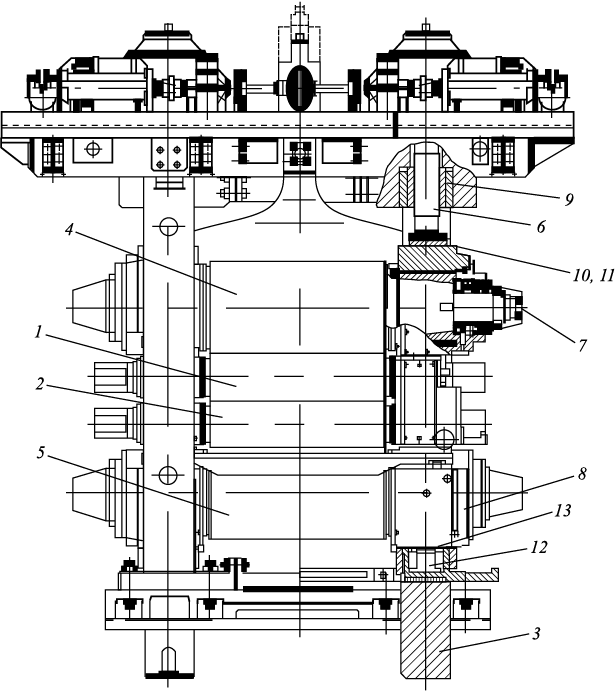
During metal reduction to the required thickness hi , the working rolls experience a rolling force Pi , which can be assumed to act vertically. This force is transmitted through all structural elements of the assembled stand, including the four-high roll system, thrust bearings with pressure capsules, back-up chocks, thrust bearings of mill screws, mill screws, packing nuts of mill screws, and close-top roll housings (Fig. 1). Classical methods for calculating elastic deformations in four-high working stands [13 – 15] are based on the assumption that all structural components deform according to the laws of elasticity. Using this assumption, the stiffness modulus of each four-high working stand in a continuous mill is determined through well-established theoretical formulas for the elastic deformation of all the aforementioned components that bear the vertical rolling force during operation. However, as noted in [13 – 15], these formulas apply only to the static stiffness modulus and do not account for key dynamic factors, such as the influence of back-up roll rotational speed on deformation within hydrodynamic bearings, the horizontal displacement of vertical axial planes of back-up and working rolls relative to each other [21], and other rolling dynamics [10 – 12] affecting all assembled stand components.
Fig. 1. Construction of four-high stand of hot rolling mill: |
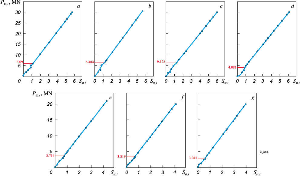
Under modern operating conditions, assessing the stiffness modulus of mill stands is most efficiently conducted using loading curves obtained by pre-stressing the rotating working rolls into the pre-stressed stand position. This method was applied to evaluate the stiffness modulus of the four-high stands in the finishing group of hot rolling mill 2000 at PAO Severstal. The loading force during the assessment was varied within the actual operating rolling force range: from 0 to 30 MN for stands 6 – 9 and from 0 to 20 MN for stands 10 – 12, while maintaining a constant working roll rotation speed equal to the average strip rolling speed in the i-th stand. To minimize the additional measurement errors, a coolant was applied to the rolls during loading before the start of measurements.
The experimental data on loading force Рld.i and total elastic deformations in the i-th finishing stand Sst.i were recorded by the automated process control system (APCS) of the finishing group of hot rolling mill 2000. The processed data were then presented graphically in Fig. 2, showing the relationship between the total loading force Рld.i of each stand and the elastic deformation of all structural elements of the stand Sst.i . The material properties and nominal diameters of the working and back-up rolls are listed in Table 1.
Fig. 2. Graphics of loading pre-stressed stands of rotating work rolls:
Table 1. Elastic material characteristics and nominal diameters
| |||||||||||||||||||||||||||||||||||||||
The stiffness modulus of the pre-stressed stand in the i-th stand \(M_{{\rm{st}}{\rm{.}}i}^0\) was determined based on the linear portion of the curves in Fig. 2, using the ratio of the loading force Рld.i to the elastic deformation of the stand Sst.i :
| \[M_{{\rm{st}}{\rm{.}}i}^0 = \frac{{{P_{{\rm{ld}}{\rm{.}}i}}}}{{{S_{{\rm{st}}{\rm{.}}i}}}}.\] | (2) |
Analysis of the curves in Fig. 2 showed that for all mill stands, the onset of the linear deformation region occurs at a loading force of 6.484 – 3.041 MN, with higher values corresponding to the first stands. As the loading force increases further, the stand deformation follows a strictly linear trend, remaining fully compliant with elasticity laws across the entire operating force range.
Determining the stiffness modulus of the pre-stressed stand \(M_{{\rm{st}}{\rm{.}}i}^0\) using equation (2), based on the data from Fig. 2, and its subsequent application without significant error is valid for rolling strips in the finishing group of hot rolling mill 2000 at a maximum width of bi = 1820 mm.
The dependence of the stiffness modulus of the four-high stands in the finishing group of hot rolling mill 2000 on the width of the rolled strip bi was investigated using the following methodology. During steady-state rolling, all stands operate under conditions of constant positioning of the screw-down mechanisms. As the strip undergoes deformation in the i-th stand, the APCS of the finishing group records the average strip thickness hi , the rolling force Pi and the average elastic deformation of the stand Sst.i . The averaged stiffness modulus of the i-th stand \(M_{{\rm{st}}{\rm{.}}i}^b\) considering the variation in strip width bi can be calculated using equation
| \[M_{{\rm{st}}{\rm{.}}i}^b = \frac{{{P_i}}}{{{S_{{\rm{st}}{\rm{.}}i}}}}.\] | (3) |
The physical meaning of this parameter \(M_{{\rm{st}}{\rm{.}}i}^b\) reflects the change in the stand’s elastic deformation due to the deflection of the roll system under the rolled strip of width bi . The difference between the stiffness modulus of the stand without a strip \(M_{{\rm{st}}{\rm{.}}i}^0\) and the calculated value obtained using equation (3) is denoted as Δ\(M_{{\rm{st}}{\rm{.}}i}^b\). Upon completion of the study, databases were compiled to record the following rolling parameters for the i-th stand:
– average strip width bi and average strip thickness hi of the rolled strip;
– value of the change in elastic deformation of the stand Sst.i ;
– calculated value of the correction factor Δ\(M_{{\rm{st}}{\rm{.}}i}^b\).
Thus, the stiffness modulus of the stand for a strip width bi less than 1820 mm, accounting for the correction factor Δ\(M_{{\rm{st}}{\rm{.}}i}^b\), can be determined using the following equation
| \[{M_{{\rm{st}}{\rm{.}}i}} = M_{{\rm{st}}{\rm{.}}i}^0 - \Delta M_{{\rm{st}}{\rm{.}}i}^b,\] | (4) |
where \(M_{{\rm{st}}{\rm{.}}i}^0\) is represents the stiffness modulus of the pre-stressed stand, MN/mm; Δ\(M_{{\rm{st}}{\rm{.}}i}^b\) is the correction factor for assessing the stiffness modulus of the i-th stand, considering the variation in rolled strip width bi , MN/mm.
Results and discussion
The dataset prepared for regression analysis was obtained from 46 rolling schedules in the finishing group of hot rolling mill 2000, covering low-carbon steel strips with thicknesses ranging from 1.2 to 5.5 mm and widths from 1005 to 1625 mm. These strips were primarily intended for further cold rolling and were processed using different sets of working and back-up rolls. During the regression analysis, linear equations (Table 2), were derived, which accurately describe the correction factor Δ\(M_{{\rm{st}}{\rm{.}}i}^b\) for the stiffness modulus of the pre-stressed stand \(M_{{\rm{st}}{\rm{.}}i}^0\) as a function of the rolled strip width bi .
Table 2. Values of stiffness modulus of pre-stressed stand \(M_{{\rm{st}}{\rm{.}}i}^0\), regression equations for Δ\[M_{{\rm{st}}{\rm{.}}i}^b\] calculation and their reliability
|
Since the actual values of Fisher’s criterion F in Table 3 significantly exceed the critical value Fcr (1; 44) = 4 at degrees of freedom k1 = 1 and k2 = 44, the determination coefficients R2 are statistically significant, confirming the reliability of the regression equations for Δ\(M_{{\rm{st}}{\rm{.}}i}^b\) in Table 2. These equations are valid within the following parameter ranges:
– working roll crown profiles from –0.5 to –0.15 mm;
– working roll diameters from 930 to 800 mm;
– back-up roll diameters from 1616 to 1488 mm;
– back-up roll chamfer depth of 0.8 mm and chamfer length of 300 mm.
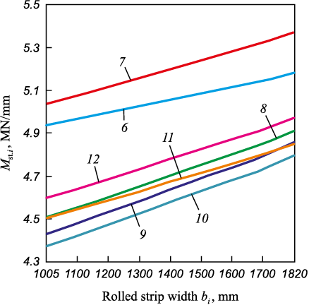
Based on the Table 3 data, graphs were plotted (Fig. 3) to illustrate the variation in the stiffness modulus Мst.i for each stand in the finishing continuous group of hot rolling mill 2000, depending on the rolled strip width bi .
Table 3. Calculated values of rolling stands stiffness modulus
Fig. 3. Graphics of change in stiffness modulus Мst.i | ||||||||||||||||||||||||||||||||||||||||||||||||||||||||||||||||||
The accuracy of determining the stiffness modulus Мst.i considering the correction factor Δ\(M_{{\rm{st}}{\rm{.}}i}^b\) for strip width variation bi , was verified by solving equation (1) and comparing the measured rolling force Pi in the i-th stand during the rolling of a 2.0 mm-thick, 1300 mm-wide strip of 08Yu steel. The initial roll gap Si was recorded by the APCS of the finishing group of hot rolling mill 2000, as shown in Table 3. The calculated and measured rolling forces, along with their comparison results, are also provided in Table 3.
Since the maximum comparison error ΔPi in Table 3 does not exceed 6.06 %, the findings of this study can be effectively applied in designing hot rolling schedules for hot rolling mill 2000. These results ensure the required longitudinal and widthwise profile accuracy of hot-rolled strips while incorporating control models for longitudinal and widthwise thickness deviations.
Conclusions
Based on the analysis of experimental data, reliable dependencies have been established that describe the effect of rolled strip width on the variation of the stiffness modulus of four-high stands in the finishing group of the operating hot rolling mill.
It has been determined that rolling within the finishing group, from the first to the last stand, with rolling forces below 6.484 – 3.041 MN is undesirable, as under such conditions, the stands experience nonlinear deformation, leading to additional fluctuations in the roll gap.
The research findings can be applied in the development of optimized rolling schedules for the finishing group of mill stands, ensuring the production of hot-rolled strips with minimal deviations in the longitudinal and widthwise geometric profile characteristics.
References
1. Garber E.A. Cold Rolling Mills. Moscow: Chermetinformatsia; 2004:416. (In Russ.).
2. Garber E.A., Kozhevnikova I.A., Tarasov P.A. Calculation of hot rolling forces of thin strips taking into account the stress-strain state in adhesion region of deformation zone. Proizvodstvo prokata. 2007;(4):7–15. (In Russ.).
3. Garber E.A., Kozhevnikova I.A., Tarasov P.A., Zavrazhnov A.A., Traino A.I. Simulation of contact stresses and forces during hot rolling of thin wide strips with allowance for a stick zone and elastic regions in the deformation zone. Russian Metallurgy (Metally). 2007;(2):112–119. https://doi.org/10.1134/S003602950702005X
4. Garber E.A., Pospelov I.D., Kozhevnikova I.A. Influence of chemical compositions and elastic properties of strip and rolls on energy and force parameters in wide-strip hot rolling mills. Proizvodstvo prokata. 2011;(8):2–7. (In Russ.).
5. Garber E.A., Kozhevnikova I.A., Tarasov P.A. Effective hot rolling modes of thin strips at wide-strip mills. Proizvodstvo prokata. 2007;(4):7–15. (In Russ.).
6. Garber E.A., Pospelov I.D., Traino A.I., Savinykh A.F., Nikolaev N.Yu., Mishnev P.A. Simulation of the longitudinal thickness deviation of the steel strips hot rolled in the continuous group of a broad-strip mill. Russian Metallurgy (Metally). 2012;(9):831–836. https://doi.org/10.1134/S0036029512090042
7. Pospelov I.D., Rumyantsev V.V. Joint regulation of longitudinal and transverse gage variations during hot rolling in finishing group of stands of continuous broadband mill. Rolling Production. Appendix to Journal “Technology of Metals”. 2024;(20):10–19. (In Russ.). https://doi.org/10.31044/1684-2499-2024-0-20-10-19
8. Wu J., Yan X. Coupling vibration model for hot rolling mills and its application. Journal of Vibroengineering. 2019;21(7):1795–1809. https://doi.org/10.21595/jve.2019.20226
9. Qi J.B., Wang X.X., Yan X.Q. Influence of mill modulus control gain on vibration in hot rolling mills. Journal of Iron and Steel Research International. 2020;27:528–536. https://doi.org/10.1007/s42243-020-00375-3
10. Wang L., Hou P., Wang S., Wang C., Yan X., Wang X. Study on the effect of rolling mill dynamic stiffness on coupled vibration of hydraulic machine. Journal of Vibroengineering. 2024;26(3):455–468. https://doi.org/10.21595/jve.2023.23524
11. Jia X.D., Wang S., Yan X.Q., Wang L.D., Wang H.P. Research on dynamic response of cold rolling mill with dynamic stiffness compensation. Electronics. 2023;12(3):0599. https://doi.org/10.3390/electronics12030599
12. Gong D.Y., Xu J.Z., Yuan F.C. Study on roll elastic deformation asymmetrical 4-high mill stiffness. Journal of Northeastern University (Natural Science). 2012; 33(11):1586–1590.
13. Tselikov A.I., Polukhin P.I., Grebenik V.M., etc. Machines and Aggregates of Metallurgical Plants: Textbook: in 3 vols. Moscow: Al`yans; 2018. (In Russ.).
14. Korolev A.A. Mechanical Equipment of Rolling and Pipe Shops: Textbook for Universities. Moscow: Metallurgiya; 1987:480. (In Russ.).
15. Grigoryan G.G., Zheleznov Yu.D., Chernyi V.A., Kuznetsov L.A., Zhuravskii A.G. Adjustment, Stabilization and Control of Thin-Sheet Rolling. Moscow: Metallurgiya; 1975. (In Russ.).
16. Wenyu M., Fenqqin W., Xibang Z., Wei G., Ziying L., Lin T. Influence of rolling force and roll gap on thickness of strip. IOP Conf. Series: Materials Science and Engineering. 2017;239:012012. https://doi.org/10.1088/1757-899X/239/1/012012
17. Laihua T., Qiaoyi W., Huajie W. Establishment and numerical analysis of rolling force model based on dynamic roll gap. Applied Sciences. 2023;13(13):7394. https://doi.org/10.3390/app13137394
18. Zhenhua W., Yu H., Yuanming L., Tao W. Prediction model of strip crown in hot rolling process based on machine learning and industrial data. Metals. 2023;13(5):900. https://doi.org/10.3390/met13050900
19. Haibo X., Xingsheng L., Tao Z. Numerical analysis of the effect of work roll bending on strip crown during tandem hot rolling. International Journal of Applied Mechanics. 2022;14(07):2250052. https://doi.org/10.1142/S1758825122500521
20. Liu G.M., Li Y.G., Huang Q.X., Yang X. Axial force analysis and roll contour configuration of four-high CVC mill. Mathematical Problems in Engineering. 2018;(2):7527402. https://doi.org/10.1155/2018/7527402
21. Garber E.A., Kozhevnikova I.A., Tarasov P.A., Traino A.I. Effect of sliding and rolling friction on the energy-force parameters during hot rolling in four-high stands. Russian Metallurgy (Metally). 2007;(6):484–491. https://doi.org/10.1134/S0036029507060080
About the Author
I. D. PospelovRussian Federation
Ivan D. Pospelov, Cand. Sci. (Eng.), Assist. Prof.
5 Lunacharskogo Ave., Cherepovets, Vologda Region 162600, Russian Federation
Review
For citations:
Pospelov I.D. Stiffness modulus of stands in finishing group of continuous wide-strip hot rolling mill. Izvestiya. Ferrous Metallurgy. 2025;68(1):14-20. https://doi.org/10.17073/0368-0797-2025-1-14-20


