Scroll to:
Influence of combined thermal effect of electric arc welding with aluminothermic backfill on internal stresses in a steel plate
https://doi.org/10.17073/0368-0797-2024-5-604-611
Abstract
The paper is devoted to automatic electric arc welding under a flux layer using filler material in the form of aluminothermic backfill for joining thick-plate structures. The plate material is assumed to be elastic-plastic, the deformations are small and consist of elastic and plastic. Reversible (elastic) deformations are associated with stresses by the Duhamel-Neumann law, irreversible (plastic) ones arise and grow due to plastic flow within the framework of the associated law of plastic flow. The modified Mises condition, which takes into account viscosity, is adopted as the condition of plastic flow. The heat source from automatic electric arc welding is modeled by a double ellipsoid proposed by John A. Goldak, and heat from chemical reaction in the region of aluminothermiс combustion front is specified by the heat flux value. Elastic moduli and yield strength depend on temperature. Plates with thicknesses of 12, 14, 16, 18 mm were considered. Comparing the intensity of residual stresses in the upper and lower layers of the plates and by their thicknesses, it can be stated that with increasing thickness, the areas of distribution of residual stresses high intensity increase and their values increase too. These areas are located inside the material in the near-weld zone in the area of blue brittleness. Analyzing straightening of temperature fields, for the case of electric arc welding with filler material in the form of aluminothermiс backfill and without it, it was found that as a result of a chemical reaction, the temperature in the weld zone increases by 500 °C, this makes it possible to use this technology for welding at low climatic temperatures.
Keywords
For citations:
Tkacheva A.V., Abashkin E.E. Influence of combined thermal effect of electric arc welding with aluminothermic backfill on internal stresses in a steel plate. Izvestiya. Ferrous Metallurgy. 2024;67(5):604-611. https://doi.org/10.17073/0368-0797-2024-5-604-611
Introduction
With the growth of production, there emerged a need for the assembly of large metal structures. This is generally achieved through welding, which negatively affects the base metal, creating irreversible deformations and increased stresses in the weld zone due to localized thermal overheating. To reduce stresses in the area affected by temperature, preheating and concurrent heating are applied [1 – 4], reducing the temperature gradient, or post-weld heat treatment is used. Mechanical impact in the weld zone by means of forging is also employed to reduce the negative effects of welding. When it comes to extended welds in thick-walled metal plates, the aforementioned methods become difficult to implement, making it more appropriate to use a filler material to perform welding in a single pass.
Automatic electric arc welding under flux using powder filler material (PFM) is intended for welding thick-walled structures with a thickness of up to 60 mm. The use of PFM increases the thermal efficiency of the process and improves the quality of the weld joint. Traditionally, filler material is used in the form of granules, which are small fragments cut from welding wire with a diameter of 0.8 – 2.0 mm. PFM is supplied to the welding zone either by pre-filling it into the gap or groove before welding, or it is fed along the electrode extension using a metering device, provided the material is ferromagnetic [5]. The key advantages of the process are higher efficiency, higher productivity, and better weld joint quality. Possible variations of electric arc multi-wire welding and surfacing with the addition of metal powder have been discussed in works [6 – 9]. PFM is also used in laser welding [10 – 13].
In the present study, aluminothermic backfill is investigated as PFM, as an aluminothermic filler in powder wire, consisting of a mixture of metal scale fractions and aluminum alloy with the addition of alloying components, has demonstrated the best performance [14 – 17]. Its use ensures uniform subsequent heating of the weld due to the combination of electric arc thermal effects and the exothermic redox reaction, during which iron is reduced from scale [18]. The slag formed as a result of the reaction has insulating properties, reducing heat dissipation from the surface of the weld and increasing the time for uniform solidification, which contributes to the formation of a fine-grained structure in the material.
Mathematical modeling allows optimizing the electric arc welding process without incurring significant costs [19 – 21].
Objective: to establish the effect of the combined thermal impact of aluminothermic backfill during the welding of thick-plate structures on the distribution of residual stress intensity and assess the possibility of using this welding technology at low ambient temperatures.
Basis of the mathematical model
We assume that at the initial moment, there are no irreversible deformations in the plate material. Deformations are considered small dij and consist of reversible eij and irreversible pij components:
| dij = 0.5(ui, j + uj, i ) = eij + pij . | (1) |
The Duhamel-Neumann relationship describes the connection between stress, elastic deformation, and temperature:
| σij = [λekk – 3αK (T – T0 )]δij + 2μeij , | (2) |
where λ, μ, \(K = \frac{2}{3}\mu + \lambda \) are the elastic moduli; α is the coefficient of linear expansion.
The elastic moduli depend on temperature. In this case, we use their linear dependence
| \[\begin{array}{c}E\left( {x,y,z,t} \right) = {E_p} - \left( {{E_p} - {E_0}} \right)\theta \left( {x,y,z,t} \right);\\v\left( {x,y,z,t} \right) = 0.5 - \left( {0.5 - {v_0}} \right)\theta \left( {x,y,z,t} \right),\\\mu = \frac{E}{{2\left( {1 + v} \right)}},{\rm{ }}\lambda = \frac{{vE}}{{\left( {1 + v} \right)\left( {1 - 2v} \right)}},{\rm{ }}\theta = \frac{{{T_p} - T}}{{{T_p} - {T_0}}},\end{array}\] | (3) |
where E0 and Ep are the Young’s moduli at room temperature T0 and at the melting point Tp respectively; and v is the Poisson’s ratio and v0 is the Poisson’s ratio at room temperature.
When the stress state reaches the yield surface in stress space, irreversible deformations begin to grow. We express the associated flow law
| \[\varepsilon _{ij}^p = d{p_{ij}} = d\varphi \frac{{\partial f\left( {{\sigma _{ij}},\eta } \right)}}{{\partial {\sigma _{ij}}}},{\rm{ }}d\varphi > 0.\] | (4) |
The Mises plastic flow condition is adopted as the yield surface
| \[\sqrt {\frac{3}{2}\left( {{\tau _{ij}} - \eta \varepsilon _{ij}^p} \right) \cdot \cdot \left( {{\tau _{ij}} - \eta \varepsilon _{ij}^p} \right)} = k,\] | (5) |
where τij = σij – δij σ0 , δij – Kronecker index, if i = j, then δij = 1, and if i ≠ j, then δij = 0; \({\sigma _0} = \frac{1}{3}\sigma_{ii} = \frac{1}{3}{\delta _{ij}}\sigma_{ij}\) k is the yield strength dependent on temperature k = k0θ2; at T = Tp k = 0.10 Pa; η is the material viscosity.
The system of equations (1) – (5) is supplemented by the equilibrium equation
| σij, j = 0. | (6) |
The boundary conditions model the free surface. The mechanical problem (1), (2), (4) – (6) is solved numerically for a given temperature field.
Problem setup
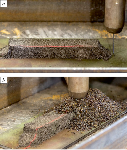
A plate made of low-carbon and low-alloy steel (St3 grade) at room temperature in an unstressed state (free-standing) is filled with a powder filler material consisting of an aluminothermic composition (backfill geometry: 40×20 mm) (Fig. 1, a) along the length of the future weld. At a speed of 20 m/h, the welding machine follows the designated path (as shown in Fig. 1, b), activating the chemical reaction in the filler material by the heat of the electric arc. The combustion front of the aluminothermic backfill moves at the same speed, slightly ahead of the welding process. The plate thickness varies from 12 to 18 mm. The diameter of the Sv-08 electrode wire is 3 mm.
Fig. 1. Experimental setup |
During arc welding, the process of heat distribution in a solid body is described by a nonlinear heat conduction equation considering the active heat source
| \[c\left( T \right)\rho \frac{{\partial T}}{{\partial t}} = {\rm{div}}\left[ {\lambda \left( T \right){\rm{grad}}T} \right] + q,\] | (7) |
where λ(T) is thermal conductivity, (W/m·°С); c(T) is specific heat capacity (J/kg·°С); ρ is density (kg/m3); q is the volumetric power density of the heat source (W/m3).
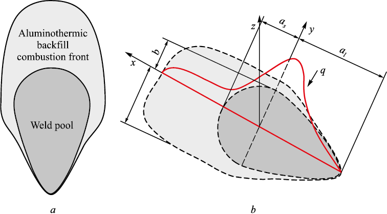
Fig. 2. Task outline |
The heat source from electric arc welding is modeled using a double ellipsoid proposed by John A. Goldak [22]. Fig. 2, b shows the shape of the heat flux in the plate during welding.
| \[\begin{array}{c}{q_s} = {f_s}\frac{{6\sqrt {3Q} }}{{{a_s}bc{\pi ^{1,5}}}}{e^{ - 3\left[ {{{\left( {\frac{{x + v\left( {\tau - t} \right)}}{{{a_s}}}} \right)}^2} + {{\left( {\frac{y}{b}} \right)}^2} + {{\left( {\frac{z}{c}} \right)}^2}} \right]}};\\{q_l} = {f_l}\frac{{6\sqrt {3Q} }}{{{a_l}bc{\pi ^{1,5}}}}{e^{ - 3\left[ {{{\left( {\frac{{x + v\left( {\tau - t} \right)}}{{{a_l}}}} \right)}^2} + {{\left( {\frac{y}{b}} \right)}^2} + {{\left( {\frac{z}{c}} \right)}^2}} \right]}},\end{array}\] | (8) |
where Q is the effective thermal power of the heating source (for arc welding Q = ηIU, in W); τ is the time since the source started, in s; t is the current time, in s; v is the welding speed, in m/s; x, y, z are the semi-axes of the ellipsoid in the OX, OY, and OZ directions, in m; fs and fl are coefficients defining the ratios for heat introduced into the front and rear parts of the ellipsoid; as , al , b, c are the respective radii of the normal distribution. Based on the above, the relationship between coefficients fs and fl is as follows:
\[{f_s} = \frac{{2{a_s}}}{{{a_s} + {a_l}}};{\rm{ }}{f_l} = \frac{{2{a_l}}}{{{a_s} + {a_l}}};{\rm{ }}{f_s} + {f_l} = 2.\]
At the front of the aluminothermic combustion zone, the boundary conditions are given as
| \[ - \lambda \left( {\frac{{\partial T}}{{\partial z}}} \right) = {q_w}\left( {x,y,z} \right),\] | (9) |
where qw (x, y, z) is the heat flux from the chemical reaction, amounting to 58 W.
On surfaces free from the heat source, boundary conditions model heat dissipation into the surrounding environment:
| \[\lambda \frac{{\partial T}}{{\partial {x_i}}} = kof\left( {T - {T_0}} \right),\] | (10) |
where kof is the heat transfer coefficient with the surrounding medium, equal to 6 W/(m2ꞏ°С). In the weld area, the slag formed by the welding process reduced heat dissipation from the plate surface to 3.5 W/(m2·°С).
Since λ and c are constants, the system of equations (7) – (10) is solved using the sweep method.
Calculation results
We consider steel plates measuring 500×150 mm with thicknesses of 12, 14, 16, and 18 mm and the following physical-mechanical characteristics: density ρ = 785 kg/m3; Young’s modulus E0 = 210 GPa at room temperature and Ep = 0.3 GPa at the melting point Tp = 1400 °C; Poisson’s ratio of 0.27; yield strength of 255 MPa at room temperature; coefficient of linear thermal expansion of 11.1·10\(^–\)6 1/°С; thermal conductivity 55.5 W/m·°C; specific heat capacity of 482 J/kg·°С); source efficiency of 90 %; current of 300 A; and voltage of 35 V.
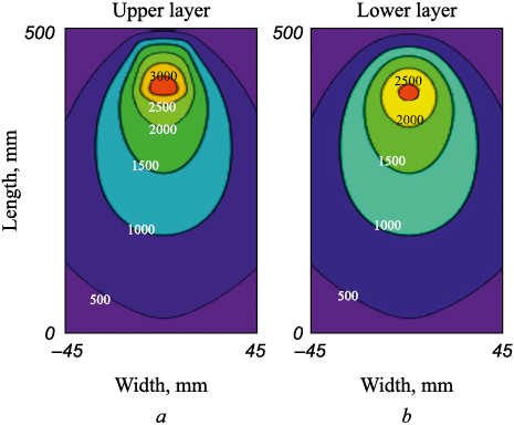
To analyze the effect of powder backfill, we will compare the thermal fields. Fig. 3 shows the distribution of the temperature field resulting from automatic electric arc welding using aluminothermic backfill and without it. The voltage-current characteristics and welding speed are identical in both cases. As can be seen, in the area of the welding arc, the temperature field with the filler material is increased by 500 °C. This allows the use of aluminothermic backfill in low ambient temperatures as preheating.
Fig. 3. Temperature distribution in the upper layer of a steel plate |
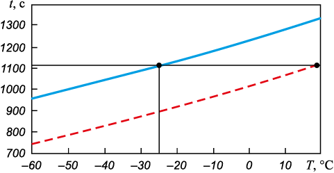
If we take the cooling time of the weld obtained by electric arc welding at room temperature as the basis for assessing the quality of the joint, then this time can also be achieved at sub-zero temperatures. Fig. 4 shows the cooling time for a plate with a thickness of 12 mm, depending on the ambient temperature. The solid line represents the use of filler material, while the dashed line represents welding without it.
Fig. 4. Cooling time of a 12 mm thick plate |
The cooling time of the weld obtained by automatic electric arc welding at 20 °C is the same as at –25 °C with the use of aluminothermic backfill, making it possible to apply this welding process at sub-zero ambient temperatures.
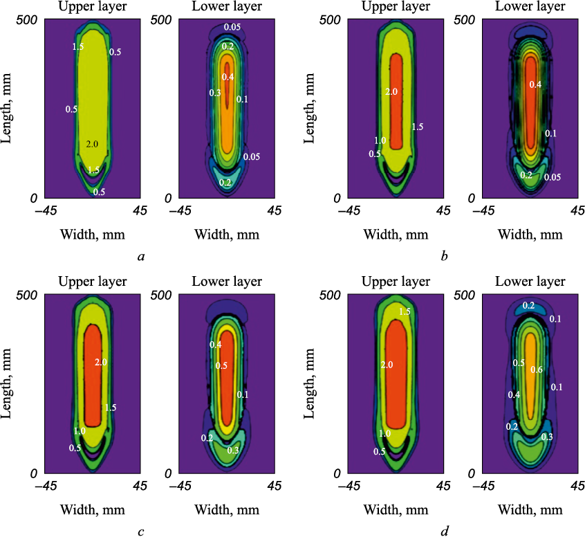
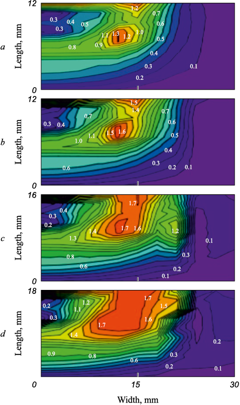
Next, let us consider the effect of plate thickness on the intensity of residual stresses formed as a result of electric arc welding at room temperature using filler material in the form of aluminothermic backfill. Fig. 5 shows the residual stress fields in the upper and lower layers of the plate. It can be seen that as the plate thickness increases, the intensity of residual stresses in the material also increases. Looking in the transverse direction at the center of the plate, the highest intensity of residual stresses is located in the area of blue brittleness and increases with plate thickness, while in the center of the weld the values are small (Fig. 6).
Fig. 5. Distribution of residual stresses intensity depending on plate thickness,
Fig. 6. Distribution of intensity of residual stresses located along the plate |
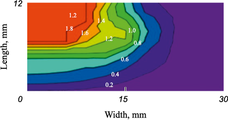
To demonstrate that the use of aluminothermic backfill during electric arc welding reduces areas with high intensity of residual stresses, we compare Fig. 6, a with Fig. 7, which shows the distribution of residual stress intensity in a weld obtained without filler material in a 12 mm thick plate. The positive effect of aluminothermic backfill is evident, as the weld obtained without filler material shows a high level of residual stress intensity covering a large area, almost half the thickness of the weld, and decreasing towards the periphery. This cannot be said for the weld made using filler material in the form of aluminothermic backfill, where the small area of high residual stress intensity is located away from the weld zone in the area of blue brittleness. The pattern (effect) of this arrangement can be compared to preheating, with the regions of high-temperature gradient located on the sides of the weld zone in the fusion area.
Fig. 7. Distribution of intensity of residual stresses located along the plate |
Conclusions
Studies were conducted on automatic electric arc welding under a flux layer using filler material in the form of aluminothermic backfill for joining thick-plate structures. It was found that the use of aluminothermic backfill reduces the intensity of residual stresses compared to traditional welding. As the plate thickness increases, both the intensity of residual stresses and the area of their distribution expand.
Due to the additional heat generated during the chemical reaction, the temperature in the material during automatic electric arc welding with aluminothermic backfill increases by 500 °C compared to welding without this filler material. This indicates that welding operations can be carried out at low ambient temperatures, while ensuring the same quality of the weld joint as would be achieved at room temperature.
References
1. Li L., Mi G., Wang Ch. A comparison between induction pre-heating and induction post-heating of laser-induction hybrid welding on S690QL steel. Journal of Manufacturing Processes. 2019;43(A):276–291. https://doi.org/10.1016/j.jmapro.2019.05.003
2. Charkhi M., Akbari D. Experimental and numerical investigation of the effects of the pre-heating in the modification of residual stresses in the repair welding process. International Journal of Pressure Vessels and Piping. 2019;171:79–91. https://doi.org/10.1016/j.ijpvp.2019.02.006
3. Ji Sh., Li Zh., Ma L. Joint formation and mechanical properties of back heating assisted friction stir welded Ti–6Al–4V alloy. Materials & Design. 2017;113:37–46. http://dx.doi.org/10.1016/j.matdes.2016.10.012
4. Tkacheva A.V., Abashkin E.E. Effect of preheating of the edge of a steel plate on the intensity of residual stresses formed as a result of electric arc welding. Marine Intelligent Technologies. 2023;(2–1(60)):304–314. (In Russ.). https://doi.org/10.37220/MIT.2023.60.2.038
5. Instructions for Automatic Submerged Arc and Electroslag Welding with Powder Filler Material (PMM) VSN 375–77. Moscow: Central Bureau of Scientific and Technical Information; 1978. (In Russ.).
6. Gorokhova M.N., Churilov D.G. Influence of polar effect and electrode material on transfer of filler powder material using the electric pulse method. Trudy GOSNITI. 2012;109(2): 51–56 (In Russ.).
7. Ranjan R., Das A.K. Protection from corrosion and wear by different weld cladding techniques: A review. Materials Today: Proceedings. 2022;57(4):1687–1693. https://doi.org/10.1016/j.matpr.2021.12.329
8. Tusek J., Suban M. High-productivity multiple-wire submerged-arc welding and cladding with metal-powder addition. Journal of Materials Processing Technology. 2003;133(1):207–213.
9. Zhilin P.L., Gavrilov G.N., Melnichenko O.P. Welding and cladding with pre-heated additional filler wire. Materials Today: Proceedings. 2021;38(4):1622–1626. https://doi.org/10.1016/j.matpr.2020.08.168
10. Shishov A.Yu., Tretyakov R.S., Tretyakov E.S., Staverty A.Ya. Prospects for the development of laser-plasma welding technology for large-thickness products in shipbuilding using powder filler material. Bulletin of the Bauman Moscow State Technical University. 2012;(6(6)):15–22. (In Russ.).
11. Zhang Zh., Zhao Y., Shan J., Wu A., Sato Y.S., Tokita Sh., Kadoi K., Inoue H., Tang X. The role of shot peening on liquation cracking in laser cladding of K447A nickel superalloy powders over its non-weldable cast structure. Materials Science and Engineering: A. 2021;823:141678. https://doi.org/10.1016/j.msea.2021.141678
12. Zhu Y., Cai Y., Wang Y. Effects of He content in shielding gases on high-efficient hybrid laser arc welding with C-276 filler metal. Journal of Materials Processing Technology. 2022;299:117367. https://doi.org/10.1016/j.jmatprotec.2021.117367
13. Alvarães C.P., Jorge C.F., Souza L., Araújo L.S., Mendes M.C., Farneze H.N. Microstructure and corrosion properties of single layer Inconel 625 weld cladding obtained by the electroslag welding process. Journal of Materials Research and Technology. 2020;9(6):16146–16158. https://doi.org/10.1016/j.jmrt.2020.11.048
14. Sergejevs D., Mikhaylovs S. Analysis of factors affecting fractures of rails welded by alumino-thermic welding. Transport Problems. 2008;3(4-2):33–37.
15. Kargin V.A., Tikhomirova L.B., Galay M.S. Improving service properties of welded joints produced by aluminothermic welding. Welding International. 2015;29(2):155–157. https://doi.org/10.1080/09507116.2014.897809
16. Manakov A.L., Abramov A.D., Ilinykh A.S., Galay M.S. Improvement of aluminothermic welding on the basis of the experimentally-theoretical research of welding seam cooling process. Journal of Physics: Conference Series. 2018;1050:012051. https://doi.org/10.1088/1742-6596/1050/1/012051
17. Tkacheva A.V., Abashkin E.E. The effect of preheating the edge of a plate made of steel 30KhGSA on the distribution of residual stresses in the electric arc process. Marine Intelligent Technologies. 2023;(3–1(61)):188–199. (In Russ.). https://doi.org/10.37220/MIT.2023.61.3.019
18. Tkacheva A.V., Abashkin E.E. Effect of local combined thermal action on the magnitude and distribution of residual stresses in a steel plate 20. Metallurg. 2023;(6):85–93. (In Russ.). https://doi.org/10.52351/00260827_2023_06_85
19. Franks J., Wheatley G., Zamani P., Nejad R.M., Macek W., Branco R., Samadi F. Fatigue life improvement using low transformation temperature weld material with measurement of residual stress. International Journal of Fatigue. 2022;164:107137. https://doi.org/10.1016/j.ijfatigue.2022.107137
20. Huang W., Wang Q., Ma N., Kitano H. Characteristics of residual stress distribution in wire-arc additive manufactured layers of low transformation temperature material. International Communications in Heat and Mass Transfer. 2023;148:107066. https://doi.org/10.1016/j.icheatmasstransfer.2023.107066
21. Feng Z., Aung T.L., Shao Ch., Lu F., Tsutsumi S., Ma N. A design method of tensile triangles and low transformation temperature weld metal for reduction of stress concentration and residual stress of welded joints. Marine Structures. 2020;72:102759. https://doi.org/10.1016/j.marstruc.2020.102759
22. Goldak J.A., Akhlagi M. Computational Welding Mechanics. New York: Springer Science & Business Media; 2006:322.
About the Authors
A. V. TkachevaRussian Federation
Anastasiya V. Tkacheva, Cand. Sci. (Phys.-Math), Senior Researcher
1 Metallurgov Str., Komsomolsk-on-Amur, Khabarovsk Territory 681005, Russian Federation
E. E. Abashkin
Russian Federation
Evgenii E. Abashkin, Cand. Sci. (Eng.), Senior Researcher
1 Metallurgov Str., Komsomolsk-on-Amur, Khabarovsk Territory 681005, Russian Federation
Review
For citations:
Tkacheva A.V., Abashkin E.E. Influence of combined thermal effect of electric arc welding with aluminothermic backfill on internal stresses in a steel plate. Izvestiya. Ferrous Metallurgy. 2024;67(5):604-611. https://doi.org/10.17073/0368-0797-2024-5-604-611


