Scroll to:
Stress-strain state of ceramic shell mold during formation of spherical steel casting in it. Part 2
https://doi.org/10.17073/0368-0797-2024-4-463-470
Abstract
The paper presents the results of numerical calculations of the solution to the problem of modeling the process of possible cracking in a spherical shell mold when pouring liquid steel into it and cooling the solidifying casting. The numerical scheme of the axisymmetric problem and the algorithm for its solution were given in Part 1. The crack resistance is estimated by magnitude of the normal stresses in the ceramic shell during its co-cooling with a solidifying casting. The results detailed analysis considered: fields of displacement, stresses, and temperatures both on spherical surface and in growing crust of solidified metal. The solution took into account the change in the shear modulus of the mold material from temperature, and an assessment of this refinement was given. The problem was solved in two ways. The first – with a constant shift modulus of the shell mold; the second – with its temperature-dependent shift modulus. There is a significant difference between these variants in terms of magnitude of the normal stresses arising in the shell mold. The authors analyzed resistance of the shell mold spherical geometry to external influences from its support filler and filling funnel. The problem of determining the contact and free surfaces at the boundary of the shell mold and support filler was solved. The results are presented graphically in the form of diagrams of stresses and temperatures over the studied area in its different sections and time intervals for cooling of the growing metal crust. The role of compressive normal stresses σ22 , σ33 on the surface of contact of the shell mold with liquid metal at the initial moment of cooling on probability of cracking in a spherical mold is shown. The level of strain-stress state in a spherical shell mold when cooling a steel casting in it is significantly determined by dependence of shift modulus of the shell mold on temperature.
For citations:
Odinokov V.I., Evstigneev A.I., Dmitriev E.A., Namokonov A.N., Evstigneeva A.A., Chernyshova D.V. Stress-strain state of ceramic shell mold during formation of spherical steel casting in it. Part 2. Izvestiya. Ferrous Metallurgy. 2024;67(4):463-470. https://doi.org/10.17073/0368-0797-2024-4-463-470
Introduction
Previous studies on the influence of the stress-strain state (SSS) on the crack resistance of shell molds (SM) during the pouring of liquid metal and subsequent cooling with the solidifying casting were conducted using shell molds for investment casting (IC) in the form of risers with both cylindrical and spherical (sump) shapes. Numerous theoretical and experimental investigations have been carried out to identify the features of the SSS in ceramic shell molds and the resulting castings in investment casting. These studies examined various factors, including the materials used in the investment models [1; 2], the shape and geometry of the SM [3; 4], the mold wall thickness [5; 6], the mold material [7; 8], the geometry of the castings [9 ‒ 11], methods for testing mold strength, and more [12; 13].
Mathematical modeling of these processes has also been presented in other works, covering modeling methods [14], research [15 ‒ 17], numerical modeling [18 ‒ 20], specialized mathematical models [21 ‒ 23], and software tools [24; 25].
The production of spherical and globular IC castings, and consequently the resistance of the SM to cracking during the formation of such castings, is of both scientific and practical interest. The materials in this study are focused on addressing this issue.
In [26], the general approach to constructing a mathematical model for determining the SSS and temperature in an SM during the cooling of a spherical casting was presented, along with the numerical scheme and algorithm for solving the problem using developed software packages [27; 28]. This study presents the results of theoretical and numerical research aimed at solving the outlined problem.
Main body
In [26], the general problem of cooling a spherical casting in a shell mold was described.
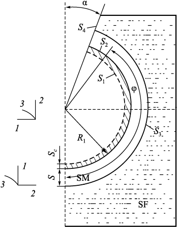
Fig. 1 illustrates the computational scheme of the process under study, considering axial symmetry (where the angle α defines the size of the gating window, and the angle φ defines the extent of the SM’s coverage by the supporting filler (SF)).
Fig. 1. Calculation scheme of a spherical ceramic shell mold |
Initial date
Geometric parameters: S = 5 mm, R1 = 20 mm.
Time intervals ∆τn : 0.1; 1.0; 2.0; 4.0; 5.0; 5.0; 5.0; 10.0; 10.0; 1.0; 2.0; 5.0; 1.0; 1.0; 3.0; 3.0; 5.0; 10.0; 10.0 s; the friction parameter on surface S3 (Fig. 1) is ψ = 0.001.
Domain partitioning: N1×N2 = 10×30.
Accepted physical parameters of the cast steel at a temperature of θ > 1000 °C (\(\theta _{\rm{м}}^*\) = 1500 °C): G = 1000 kg/mm2 (shear modulus); α = 12∙10\(^‒\)6 °С\(^‒\)1 (coefficient of linear expansion); λ = 0.0298 W/(mm∙°C) (thermal conductivity coefficient); L = 270·103 J/kg (latent heat of fusion); C = 444 J/(kg·°C) (specific heat capacity); γ = 7.80·10\(^‒\)6 kg/mm3 (density); θs = 1450 °C (solidification temperature).
Physical properties of the ceramic mold: Gm = 2910 kg/mm2; α = 0.51·10\(^‒\)6 °С\(^‒\)1; λ = 0.000812 W/(mm·°C); C = 840 J/(kg·°C); γ = 2.0·10\(^‒\)6 kg/mm3.
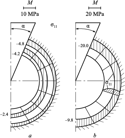
Some theoretical studies [29] have shown that during the cooling of steel in an SM with α angles of 10 and 30° and φ = (180° – α), significant compressive stresses σ22 and σ33 can occur, potentially exceeding the compressive strength of the ceramic material. When α = 30°, the stresses σii , i = 2, 3 are slightly lower in absolute value than at α = 10°. Fig. 2 shows the distribution of normal stresses σii in the SM at α = 10°: (a) after 7.1 s of cooling, (b) after 51.1 s.
Fig. 2. Diagrams of normal stresses σ11 in shell mold at α = 10° |
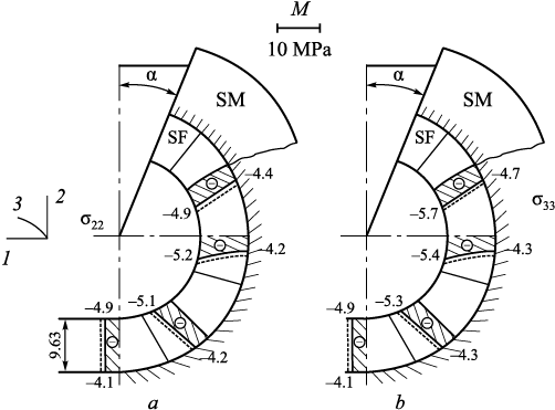
Fig. 3 illustrates the distribution of stresses σ22 and σ33 in the solidified metal shell after 60.1 s of cooling; solid lines represent the distributions at α = 30°, while dashed lines represent those at α = 10°.
Fig. 3. Diagrams of normal stresses σ22 (а) and σ33 (b) |
The values of σ22 and σ33 on the surface adjacent to the liquid metal are greater (in magnitude) than on the surface of the SM, which is explained by the constant shear modulus Gm of the forming solid metal (1000 kg/mm2), independent of temperature. As in the SM, the stresses σ22 and σ33 are compressive, and at α = 10°, they are higher than α = 30°.
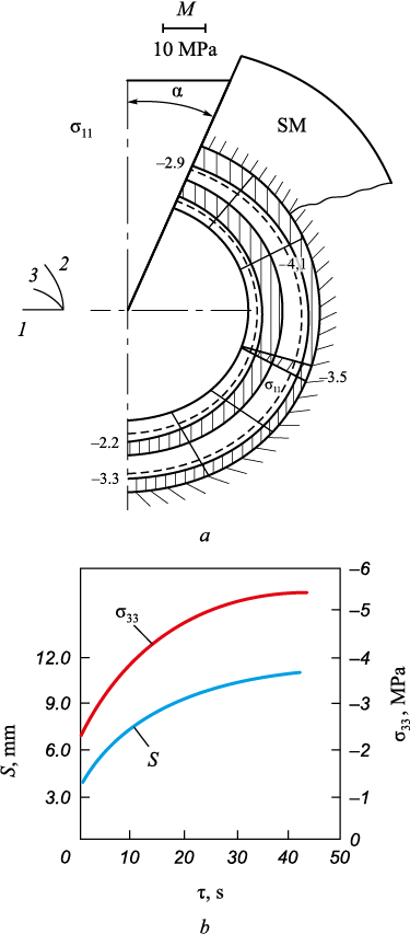
Fig. 4, а shows the distribution of stresses σ11 in the solidified metal skin after 60.1 s. The stresses σ11 are compressive throughout the cross-section: solid lines indicate σ11 at α = 30°, while dashed lines show them at α = 10°.
Fig. 4. Diagrams of normal stresses σ11 (а) in crystallized metal crust |
Fig. 4, b shows the growth curves of the skin thickness (S) and the stress σ33 over time. As the angle α increases, the normal stresses decrease slightly (in magnitude).
Further increasing α is unnecessary, as the metal skin continues to grow with only minor changes in normal stresses.
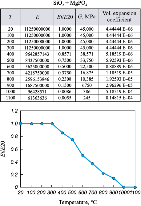
The results were obtained assuming a constant (average) shear modulus for the SM (Gm ).
As indicated in [29], the temperature in the SM adjacent to the solidifying metal is very high (around 1300 °C). At this temperature, the ceramic is practically in a softened state, meaning the shear modulus in this area will be much lower than the average value of Gm for the shell mold. We will use experimental data (Fig. 5) obtained in [30] from testing ceramic samples made from a binder material (SiO2 + MgPO4 ).
Fig. 5. Experimental data on tests of ceramic samples |
Approximating the results presented in Fig. 5, we obtain:
Gm = 6412 – 6.37θ, kg/mm2 for 300 °С < θ < 1000 °С;
Gm = 40 kg/mm2 for θ ≥ 1000 °С;
Gm = 4500 kg/mm2 for θ < 300 °С.
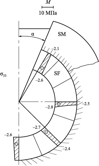
The results of the solution with a temperature-dependent shear modulus of the SM are shown in Fig. 6 at α = 10° as distributions of σii , i = 1, 2, 3 for τ = 1.12 s (solid lines); τ = 7.12 s (dashed lines).
Fig. 6. Temperatures field (a), diagrams of normal stresses σ22 (b) |
During thermal shock and cooling at τ = 1.12 s, the stresses σ22 and σ33 have the highest values (in absolute terms) in the SM’s contact zone with the metal, but they change sharply with cooling time. All normal stresses are compressive. The stresses σ33 in the forming skin (S = 6 mm) after τ = 7.12 s are shown in Fig. 7.
Fig. 7. Diagrams of normal stresses σ33 in resulting metal crust |
With further cooling, the stresses σii decrease.
The most critical period for failure is the initial cooling phase (0 < τ < 8 s) (Fig. 6).
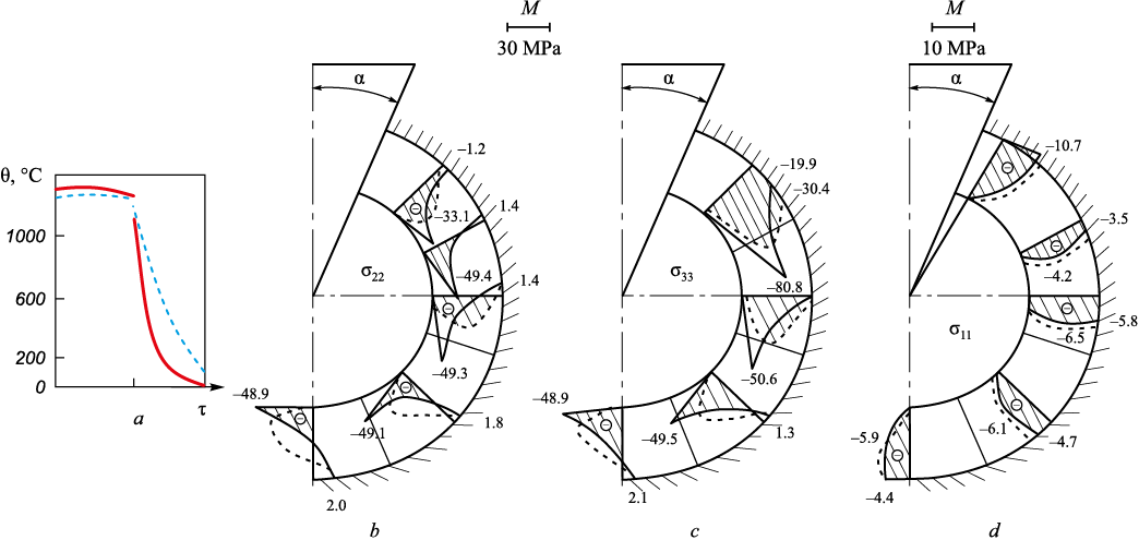
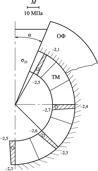
Figs. 8 and 9 show the calculation results for α = 30°, τ = 1.12 s (solid lines); τ = 7.12 s (dashed lines).
Fig. 8. Temperatures field (a), diagrams of normal stresses σ22 (b), σ33 (c) and σ11 (d) at α = 30°
Fig. 9. Diagrams of normal stresses σ33 in formed metal crust |
As seen, the pattern is approximately the same, but the values of σii , i = 1, 2, 3 are slightly lower than at α = 10°, and small tensile stresses σ22 and σ33 have even appeared in the SM at the interface with the SF (Fig. 8). In the metal skin (S = 6 mm) after τ = 7.12 s, the stresses σ33 are shown (Fig. 9), which are also lower than at α = 10° (Fig. 3, b).
Further cooling shows that normal stresses decrease, and the distributions of σii for τ = 32.12 and 52.12 s are close to each other.
Regarding the effect of the cylindrical SM material on its durability, these results were presented in previous works by the authors, where in the case under consideration, the most critical factor for potential crack formation in the SM is the tensile normal stresses σ22 in the outer layer of the shell, which is in contact with the supporting filler.
Considering the temperature dependence of the shear modulus in the SM significantly affects the stress-strain state during the cooling of the steel casting within it. Under the given external conditions for the metal cooling process in a spherical SM, its durability at the initial moment of pouring is questionable.
Conclusions
A more accurate solution to the problem was obtained by considering the temperature-dependent change in the shear modulus of the mold material, which significantly impacted the results. The analysis of the SSS in a spherical SM during the pouring of a steel casting showed that compressive stresses σ22 and σ33 at the interface between the SM and the liquid metal at the initial cooling stage are critical. Significant compressive stresses σ11 (up to 10 MPa) at the interface between the SM and the SF indicate the possibility and necessity of further theoretical study of this process by modeling the surface coverage area of the SF.
References
1. Bansode S.N., Phalle V.M., Mantha S.S. Optimization of process parameters to improve dimensional accuracy of investment casting using Taguchi approach. Advances in Mechanical Engineering. 2019;11(4):1–12. https://doi.org/10.1177/1687814019841460
2. Mittal Y.G., Kamble P., Gote G., Patil Y., Patel A. K., Bernard A., Karunakaran K.P. Mathematical Modelling of Pattern Sublimation in Rapid Ice Investment Casting. International Journal of Metalcasting. 2022;16(2):1002–1009. http://dx.doi.org/10.1007/s40962-021-00665-w
3. Kanyo J.E., Schafföner S., Uwanyuze R.Sh., Leary K.S. An overview of ceramic molds for investment casting of nickel superalloys. Journal of the European Ceramic Society. 2020;40(15):4955–4973. https://doi.org/10.1016/j.jeurceramsoc.2020.07.013
4. Rafique M.M.A., Iqbal J. Modeling and simulation of heat transfer phenomena during investment casting. International Journal of Heat and Mass Transfer. 2009;52:7–8:2132–2139. http://doi.org/10.1016/j.ijheatmasstransfer.2008.11.007
5. Singh R. Mathematical modeling for surface hardness in investment casting applications. Journal of Mechanical Science and Technology. 2012;26:3625–3629. http://dx.doi.org/10.1007/s12206-012-0854-0
6. Jafari H., Idris M. H., Ourdjini A. Effect of thickness and permeability of ceramic shell mould on in situ melted AZ91D investment casting. Applied Mechanics and Materials. 2014;465–466:1087–1092. http://dx.doi.org/10.4028/www.scientific.net/AMM.465-466.1087
7. Bansode S.N., Phalle V.M., Mantha S. Taguchi approach for optimization of parameters that reduce dimensional variation in investment casting. Archives of Foundry Engineering. 2019;19(1):5–12. https://dx.doi.org/10.24425/afe.2018.125183
8. Pattnaik S., Karunakar D.B., Jha P.K. Developments in investment casting process ‒ A review. Journal of Materials Processing Technology. 2012;212(11):2332–2348. https://doi.org/10.1016/j.jmatprotec.2012.06.003
9. Zhang J., Li K.W., Ye H.W., Zhang D.Q., Wu P.W. Numerical simulation of solidification process for impeller investment casting. Applied Mechanics and Materials. 2011;80–81: 961–964. https://doi.org/10.4028/www.scientific.net/AMM.80-81.961
10. Dong Y.W., Li X.L., Zhao Q., Jun Y., Dao M. Modeling of shrinkage during investment casting of thin walled hollow turbine blades. Journal of Materials Processing Technology. 2017;244:190–203. https://doi.org/10.1016/j.jmatprotec.2017.01.005
11. Rakoczy Ł., Cygan R. Analysis of temperature distribution in shell mould during thinwall superalloy casting and its effect on the resultant microstructure. Archives of Civil and Mechanical Engineering. 2018;18(4):1441–1450. https://doi.org/10.1016/j.acme.2018.05.008
12. Yameng W., Zhigang L. The design of testing methods for strength of ceramic shell mold in investment casting. Proceedings of the Asia-Pacific Conf. on Intelligent Medical 2018 & Int. Conf. on Transportation and Traffic Engineering. 2018;336–341. https://doi.org/10.1145/3321619.3321686
13. Kolczyk J., Zych J. High temperature strength of ceramic moulds applied in the investment casting method. Archives of Foundry Engineering. 2011;11(3):121–124.
14. Anglada E., Meléndez A., Maestro L., Domínguez I. Finite element model correlation of an investment casting process. Materials Science Forum. 2014;797:105–110. http://dx.doi.org/10.4028/www.scientific.net/MSF.797.105
15. Liu C., Sun J., Lai X., He B., Li F. Influence of complex structure on the shrinkage of part in investment casting process.The International Journal of Advanced Manufacturing Technology. 2015;77:1191–1203. https://doi.org/10.1007/s00170-014-6523-y
16. Liu C., Wang F., Jin S., Li F., Lai X. Permafrost analysis methodology (PAM) for ceramic shell deformation in the firing process. International Journal of Metalcasting. 2019;13(4):953–968. http://dx.doi.org/10.1007/s40962-019-00317-0
17. Everhart W.A., Lekakh S.N., Richards V., Chen J., Li H., Chandrashekhara K. Corner strength of investment casting shells. International Journal of Metalcasting. 2013;7:21‒27. https://doi.org/10.1007/BF03355541
18. Sabau A.S. Numerical simulation of the investment casting process. Transactions of American Foundry Society. 2005;113:407–417.
19. Zheng K., Lin Y., Chen W., Liu L. Numerical simulation and optimization of casting process of copper alloy water-meter shell. Advances In Mechanical Engineering. 2020;12(5):1–12. http://dx.doi.org/10.1177/1687814020923450
20. Manzari M.T., Gethin D.T., Lewis R.W. Optimisation of heat transfer between casting and mould. International Journal of Cast Metals Research. 2000;13(4):199‒206. https://doi.org/10.1080/13640461.2000.11819402
21. Rafique M.M.A., Shah U. Modeling and simulation of heat transfer phenomenon related to mold heating during investment casting. Engineering. 2020;12(5):291–314. http://dx.doi.org/10.4236/eng.2020.125024
22. Dong Y., Bu K., Zhang D. Numerical simulation of displacement field of solidification process for investment casting. In: 2008 Asia Simulation Conf. – 7th Int. Conf. on System Simulation and Scientific Computing. 2008:715–720. https://doi.org/10.1109/asc-icsc.2008.4675453
23. Upadhya G.K., Das S., Chandra U., Paul A.J. Modelling the investment casting process: a novel approach for view factor calculations and defect prediction. Applied Mathematical Modelling. 1995;19(6):354–362. https://doi.org/10.1016/0307-904X(95)90001-O
24. Khan M.A.A., Sheikh A.K. Simulation tools in enhancing metal casting productivity and quality: A review. Proceedings of the Institution of Mechanical Engineers, Part B: Journal of Engineering Manufacture. 2016;230(10):1799–1817. https://doi.org/10.1177/0954405416640183
25. Banerjee S., Sutradhar G. Analysis of casting defects in investment casting by simulation. Advances in Materials, Mechanical and Industrial Engineering: Selected Contributions from the First Int. Conf. on Mechanical Engineering, Jadavpur University, Kolkata, India. Springer International Publishing. 2019:247–271. http://dx.doi.org/10.1007/978-3-319-96968-8_12
26. Odinokov V.I., Evstigneev A.I., Dmitriev E.A., Namokonov A.N., Evstigneeva A.A., Chernyshova D.V. Stress-strain state of ceramic shell mold during formation of spherical steel casting in it. Part 1. Izvestiya. Ferrous Metallurgy. 2024;67(2):211‒218. https://doi.org/10.17073/0368-0797-2024-2-211-218
27. Odinokov V.I., Prokudin A.N., Sergeeva A.M., Sevast’anov G.M. Certificate of state registration of a computer program no. 2012111389. ODYSSEUS. Registered in the Register of Computer programs on 13.12.2012. (In Russ.).
28. Odinokov V.I., Dmitriev E.A., Evstigneev A.I., Ivankova E.P. Certificate of state registration of the computer program No. 2021111121 “Program for mathematical modeling the optimization of choice of temperature of the support filler, material physical properties and structure of shell mold according to smelted models to increase its crack resistance when cooling the casting in it”. Registered in the Register of Computer programs on 04.11.2021. (In Russ.).
29. Evstigneev A.I., Odinokov V.I., Dmitriev E.A., Chernyshova D.V., Evstigneeva A.A., Ivankova E.P. On the crack resistance of a ceramic shell mold according to smelted models when a spherical steel casting solidifies in it. Liteinoe proizvodstvo. 2022;(9):22–25. (In Russ.).
30. Odinokov V.I., Kaplunov B.G., Peskov A.V., Bakov A.V. Mathematical Modeling of Complex Technological Processes. Moscow: Nauka; 2008:178. (In Russ.).
About the Authors
V. I. OdinokovRussian Federation
Valerii I. Odinokov, Dr. Sci. (Eng.), Prof., Chief Researcher of the Department of Research Activities
27 Lenina Ave., Komsomolsk-on-Amur, Khabarovsk Territory 681013, Russian Federation
A. I. Evstigneev
Russian Federation
Aleksei I. Evstigneev, Dr. Sci. (Eng.), Prof., Chief Researcher of the Department of Research Activities
27 Lenina Ave., Komsomolsk-on-Amur, Khabarovsk Territory 681013, Russian Federation
E. A. Dmitriev
Russian Federation
Eduard A. Dmitriev, Dr. Sci. (Eng.), Assist. Prof., Rector
27 Lenina Ave., Komsomolsk-on-Amur, Khabarovsk Territory 681013, Russian Federation
A. N. Namokonov
Russian Federation
Aleksandr N. Namokonov, Postgraduate
27 Lenina Ave., Komsomolsk-on-Amur, Khabarovsk Territory 681013, Russian Federation
A. A. Evstigneeva
Russian Federation
Anna A. Evstigneeva, Student
27 Lenina Ave., Komsomolsk-on-Amur, Khabarovsk Territory 681013, Russian Federation
D. V. Chernyshova
Russian Federation
Dar’ya V. Chernyshova, Postgraduate
27 Lenina Ave., Komsomolsk-on-Amur, Khabarovsk Territory 681013, Russian Federation
Review
For citations:
Odinokov V.I., Evstigneev A.I., Dmitriev E.A., Namokonov A.N., Evstigneeva A.A., Chernyshova D.V. Stress-strain state of ceramic shell mold during formation of spherical steel casting in it. Part 2. Izvestiya. Ferrous Metallurgy. 2024;67(4):463-470. https://doi.org/10.17073/0368-0797-2024-4-463-470


