Scroll to:
Stress state of billet – mandrel system during production of hollow steel billet in a unit of continuous casting and deformation. Part 2
https://doi.org/10.17073/0368-0797-2024-4-457-462
Abstract
The paper presents the results of theoretical research of stress-strain state of a billet – mandrel system when producing steel hollow billets in a unit of combined continuous casting and deformation, in which the working surface of the calibrated anvils are made with a variable radius. The necessity of making the working surface of the calibrated anvils with a variable radius is substantiated and initial data for the calculations is given. The calculation results are considered along the lines of the volumetric model passing through the characteristic points of deformation centers. The authors determined the forces when the anvils compress the wall of a hollow billet and the force of pulling the hollow billet from the mold. The laws of metal axial displacements and stresses in the deformation centers during compressing the wall of a hollow billet was established at the combined process of continuous casting and deformation in the unit. Nature of the stressed state of the metal wall of a hollow billet is considered from the perspective of improving its quality. The technique studied allows to determine the stress-strain state of a mandrel when producing a hollow steel billet using such a unit. The authors provided the recommendations for reliable gripping and compression with calibrated anvils of a hollow steel billet coming from a water-cooled copper mold of the unit of combined continuous casting and deformation.
For citations:
Lekhov O.S., Mikhalev A.V., Nepryakhin S.O. Stress state of billet – mandrel system during production of hollow steel billet in a unit of continuous casting and deformation. Part 2. Izvestiya. Ferrous Metallurgy. 2024;67(4):457-462. https://doi.org/10.17073/0368-0797-2024-4-457-462
Introduction
The study [1] presents the results of calculating the stress-strain state of the metal in the deformation centers during the production of steel hollow billets in a unit of continuous casting and deformation, where the working surfaces of the anvils are made with a constant radius. This paper presents the results of calculating the bending zone and the deformation center of the tube during the compression of the billet by 5 mm with simultaneous lowering of the anvil by 5 mm, where the anvil’s working surface is made with a variable radius. This configuration allows for reliable gripping and compression of the hollow billet by the anvils as it exits the unit’s mold.
Calculation results
The simulation involved compressing billet by 5 mm (anvil movement of ‒5 mm along the X-axis) with simultaneously lowering the anvil by 5 mm (anvil movement of ‒5 mm along the Z-axis).
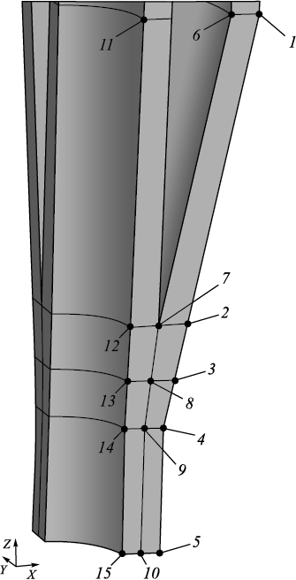
The results are presented through points along lines in the Y = 0 plane (Fig. 1).
Fig. 1. Location of points for representing the calculation results |
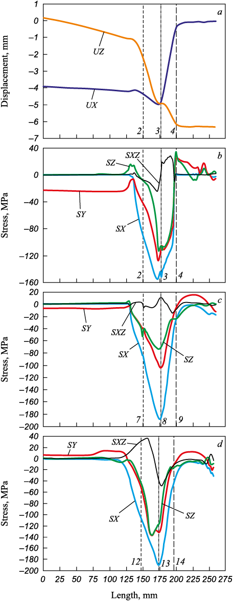
The nature of the displacements and stresses is illustrated in Figs. 1 and 2.
Fig. 2. Patterns of displacements (а) and stresses (b, c, d) |
In the Cartesian coordinate system, the displacement and stress lines align with those in the cylindrical coordinate system [2 ‒ 4].
During compression of the hollow billet wall by the anvils, the force along the X-axis is 694 kN, and along the Y-axis, it is 384 kN. The pulling force of the billet from the crystallizer along the Z-axis is 41 kN.
In addition to the graphs (Fig. 2), Table 1 provides specific values of displacements and stresses at points 1 ‒ 15. Since the maximum and minimum values of the parameters are not always located at these points, the maximum and minimum displacements and stresses along these three lines are also provided.
Table 1. Results of calculation of displacements
| ||||||||||||||||||||||||||||||||||||||||||||||||||||||||||||||||||||||||||||||||||||||||||||||||||||||||||||||||||||||||||||||||||||||||||||||||||||||||||||||||||||||||||||||||||||||||
From the data, it is evident that along the length of the deformation center (line 2 ‒ 3 ‒ 4), at point 3, the billet wall is compressed by 5 mm with simultaneous movement of the billet by 5 mm in the casting direction (Table 1, Fig. 2, a). Notably, when the hollow billet wall is compressed by the calibrated anvils, the metal displacement along the X-axis decreases to 3 mm (point 8), while along the Z-axis, it increases to 6.6 mm (Fig. 2, b, point 9).
When compressing the hollow billet with anvils designed with a variable radius working surface, the nature of the metal’s stressed state in the deformation center changes [5 ‒ 7]. In this case, the highest compressive stresses arise in the billet wall along the X-axis and line 3 ‒ 8 ‒ 13, with values of ‒152.0, ‒187.5, and ‒190.0 MPa, respectively (Table 1, Figs. 2, c, d, 3). The maximum compressive stress (‒190 MPa) occurs at the contact surface between the hollow billet wall and the mandrel (Table 1, point 13).
Calculation of the stress-strain state of the mandrel
The stress-strain state of a mandrel with a diameter of 60 mm and a channel diameter of 10 mm was calculated. This was done by solving an elastoplastic problem using the finite element method within the ANSYS software package [8 – 10].
The simulation involved compressing the billet by 5 mm (anvil movement of ‒5 mm along the X-axis) while simultaneously lowering the anvil by 5 mm (anvil movement of ‒5 mm along the Z-axis).
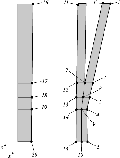
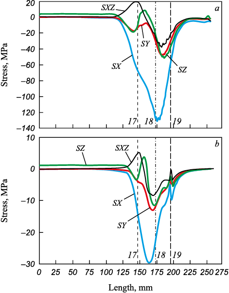
The calculation results are provided along the line passing through points 16 ‒ 20 (Fig. 3). The stress distribution is shown in Fig. 4. In addition to the graphs, Table 2 provides specific values of displacements and stresses at points 16 ‒ 20. Since the maximum and minimum values of the parameters are not always located at these points, the maximum and minimum displacements and stresses along this line are also provided [14 ‒ 16].
Fig. 3. Location of points for representing the calculation results of the mandrel
Fig. 4. Stress patterns along the lines passing through the points 16 – 17 – 18 – 19 – 20:
Table 2. Results of calculation at the lines’ points,
| |||||||||||||||||||||||||||||||||||||||||||||||||||||||||||||||||
The data indicate that at the contact surface between the mandrel and the billet wall in the deformation center (along line 17 ‒ 18 ‒ 19), the mandrel experiences maximum compressive stresses (‒130.8 MPa) in the direction of the X-axis. This should be considered when selecting the structural parameters and material for the mandrel [17 – 20].
Conclusion
The regularities of metal displacement and axial stress distribution in the deformation centers during the compression of the hollow billet wall by anvils with a variable radius working surface have been determined. The stressed state of the mandrel during the production of steel hollow billets in a unit of combined continuous casting and deformation processes has also been established.
References
1. Lekhov O.S., Mikhalev A.V., Nepryakhin S.O. Stressed state of the billet – mandrel system during production of hollow steel billet in a unit of continuous casting and deformation. Part 1. Izvestiya. Ferrous Metallurgy. 2023;66(4):485–491. https://doi.org/10.17073/0368-0797-2023-4-485-491
2. Vyunnenberg K. Production of continuously cast billets with the highest quality. In: Proceedings of the 6th Int. Congress of Iron and Steel, vol. 3. Moscow: Mashinostroenie; 1990: 364–376.
3. Fujii Н., Ohashi Т., Hiromoto Т. On the formation of the internal cracks in continuously cast slabs. Tetsu-to-Hagane. 1978;18(8):510–518. https://doi.org/10.2355/tetsutohagane1955.62.14_1813
4. Sorimachi K., Emi Т. Elastoplastic stress analysis of bulging as a major cause of internal cracks in continuously cast slabs. Tetsu-to-Hagane. 1977;63(8):1297–1304. https://doi.org/10.2355/tetsutohagane1955.63.8_1297
5. Lekhov O.S., Mikhalev A.V. Continuous Casting and Deformation Unit for the Manufacture of Steel Sheets and Billets. Ekaterinburg: UPI; 2020:307. (In Russ.).
6. Lekhov O.S., Guzanov B.N., Lisin I.V., Bilalov D.Kh. Study of combined continuous casting and cyclic deformation process for production of steel sheets. Stal’.2016;(1):59–62. (In Russ.)
7. Lekhov O.S., Mikhalev A.V., Shevelev M.M. Load and strain status of CCM backups and stripe deformation at production of steel sheets for welded pipes. Report 1. Izvestiya. Ferrous Metallurgy. 2018;61(4):268–273. (In Russ.). https://doi.org/10.17073/0368-0797-2018-4-268-273
8. ANSYS. Structural Analysis Guide. Rel. 15.0.
9. Bogatov A.A., Nukhov D.Sh., P’yankov K.P. Finite element modeling of plate rolling. Metallurg. 2015;(2):19–23. (In Russ.).
10. Takashima Y., Yanagimoto I. Finite element analysis of flange spread behavior in H-beam universal rolling. Steel Research International. 2011;82(10):1240–1247. https://doi.org/10.1002/srin.201100078
11. Karrech A., Seibi A. Analytical model of the expansion in of tubes under tension. Journal of Materials Processing Technology. 2010;210:336–362.
12. Kazakov A.L., Spevak L.F. Numeral and analytical studies of nonlinear parabolic equation with boundary conditions of a special form. Applied Mathematical Modelling. 2013; 37(10–13):6918–6928. https://doi.org/10.1016/j.apm.2013.02.026
13. Kobayashi S., Oh S.-I., Altan T. Metal Forming and Finite-Element Method. New York: Oxford University Press; 1989:377.
14. Jansson N. Optimized sparse matrix assembly in finite element solvers with one-sided communication. In: High Performance Computing for Computational Science – VECPAR 2012. Springer: Berlin, Heidelberg; 2013:128–139.
15. Matsumia Т., Nakamura Y. Mathematical model of slab bulging during continuous casting. In: Applied Mathematical and Physical Models in Iron and Steel Industry. Proceedings of the 3rd Process Tech. Conf., Pittsburgh, Pa, 28–31 March 1982. New York; 1982:264–270.
16. Park C.Y., Yang D.Y. A study of void crushing in large forgings: II. Estimation of bonding efficiency by finite-element analysis. Journal of Materials Processing Technology. 1997; 72(1):32–41.
17. Efimenko L.A., Prygaev A.K. Determination of the Actual Mechanical Properties of Pipeline Metal Based on Hardness Measurement. Moscow: RTU nefti i gaza; 2007:18. (In Russ.).
18. Kudrya A.V. Critical factors of metallurgical quality of high-strength steels. In: Perspective Materials. Vol. V. Tolyatti: TSU; 2013: 332–362. (In Russ.).
19. Kazakov A.A., Kiselev D.V. Modern methods for assessing the quality of the structure of materials based on panoramic studies based on the TXIXOMET image analyzer. In: Perspective Materials. Vol. V. Tolyatti: TSU; 2013:270–329. (In Russ.).
20. Kyung-Moon L., Hu-Chul L. Grain refinement and mechanical properties of asymmetrically rolled low carbon steel. Journal of Materials Processing Technology. 2010;210(12):1574–1579. https://doi.org/10.1016/j.jmatprotec.2010.05.004
About the Authors
O. S. LekhovRussian Federation
Oleg S. Lekhov, Dr. Sci. (Eng.), Prof. of the Chair of Engineering and Vocational Training in Machinery and Metallurgy
11 Mashinostroitelei Str., Yekaterinburg 620012, Russian Federation
A. V. Mikhalev
Russian Federation
Aleksandr V. Mikhalev, Cand. Sci. (Eng.), General Director
28 Sakko i Vantsetti Str., Pervouralsk, Sverdlovsk Region 623107, Russian Federation
S. O. Nepryakhin
Russian Federation
Sergei O. Nepryakhin, Cand. Sci. (Eng.), Assist. Prof. of the Chair of Metal Forming
28 Mira Str., Yekaterinburg 620002, Russian Federation
Review
For citations:
Lekhov O.S., Mikhalev A.V., Nepryakhin S.O. Stress state of billet – mandrel system during production of hollow steel billet in a unit of continuous casting and deformation. Part 2. Izvestiya. Ferrous Metallurgy. 2024;67(4):457-462. https://doi.org/10.17073/0368-0797-2024-4-457-462


