Scroll to:
Effect of electric arc surfacing on the structure and properties of coatings
https://doi.org/10.17073/0368-0797-2024-4-433-439
Abstract
Surfacing, like welding, is associated with heating metals in a wide range of temperatures and subsequent cooling of heated zones at different rates. This leads to complex structural and phase changes that are crucial for operational properties of the “protected material – coating” joint. The structure and properties of the alloyage zone of these two materials depend on the degree of penetration, nature of the intermediate layers that arise, and carbon diffusion in the boundary areas. When surfacing on low-carbon steel, depending on the composition of the deposited metal, the structures with a predominant amount of martensite or austenite can be obtained in the alloyage zone, depending on carbon content. The structure and mechanical properties of the bimetallic joint between carbon steel and stainless steel were studied depending on the modes of electric arc surfacing (submerged arc surfacing in one pass, in argon for one and two passes). It was established that the structural and phase composition of the deposited metal is austenite, finely dispersed carbides and a needle component. The structure of the layer deposited in argon in one pass is more homogeneous and does not contain defects. The microhardness increases smoothly along the depth of the deposited layer. As a result of surfacing in argon in two passes, the joint has a homogeneous microstructure, but a large number of microdefects are formed in the layer, which can further lead to the formation of a crack near the alloyage boundary. In submerged surfacing, the heating rate and specific heat input are insufficient, therefore, the surfacing bath is poorly mixed, which leads to a suboptimal structure and the formation of thermal stresses at the alloyage boundary and to the formation of a coating that is heterogeneous in structure and microhardness.
Keywords
For citations:
Shlyakhova G.V., Danilov V.I. Effect of electric arc surfacing on the structure and properties of coatings. Izvestiya. Ferrous Metallurgy. 2024;67(4):433-439. https://doi.org/10.17073/0368-0797-2024-4-433-439
Introduction
In many industries, such as chemical, nuclear, aerospace, and others, the structural strength of components is often determined by the materials’ resistance to aggressive environments. Technically, this challenge can be fully addressed by using corrosion-resistant materials [1 – 3]. However, from an economic stand-point, such a solution may not always be rational, particularly in applications like the secondary coolant circuits in nuclear power plants. While corrosion-resistant steel is essential for manufacturing pipelines, high-quality carbon steels can be used for valves and some pump components, provided that anticorrosion coatings are applied to the surfaces exposed to the coolant [4]. One of the most widespread and effective methods for applying such coatings is electric arc surfacing [5 – 7]. Currently, the scientific principles of electric arc surfacing are well established, and numerous modifications of this method exist. Electric arc surfacing is easily mechanized, ensuring high productivity. It allows for the uniform application of metal layers with the desired physical and mechanical properties, thus fulfilling the required technological objectives [8 – 12]. In the present study, the goal was to protect valves made of low-carbon steel from aggressive liquids. Challenges arose when transitioning from previously used surfacing materials to new ones.
Surfacing, like welding, involves heating metals over a wide temperature range and subsequently cooling the heated zones at different rates. This leads to complex structural and phase changes, which play a critical role in determining the operational properties of the “protected material – coating” joint [15]. The coating is formed during the crystallization of the molten electrode metal and the fused base metal, acquiring a cast structure. The characteristics of the aloyage zone between the deposited layer and the base material are particularly important for the properties and performance of the coating, especially when they differ in composition and structural class. The aloyage zone determines the reliability of the bond between the deposited metal and the base material [14 – 16]. The base material is low-carbon steel, while the deposited metal is stainless steel. The structure and properties of the aloyage zone between these two materials will depend on the degree of penetration, the nature of the intermediate layers that form, and carbon diffusion in the boundary areas [17; 18]. When surfacing low-carbon steel, depending on the composition of the deposited metal, the aloyage zone may develop structures with a predominant amount of martensite or austenite, depending on the carbon content. The deposited metal, depending on the chromium and nickel content, may exhibit an austenitic or austenitic-ferritic structure. If the nickel and chromium content is insufficient, the deposited metal may develop a secondary austenitic-martensitic structure [4; 8; 19]. The properties of the depos-ited metal and the resulting structure of the surfacing layer are significantly influenced by the mixing of the base metal and the electrode material. Generally, minimal mixing of the deposited metal with the base metal is desired. When stainless steels are deposited onto unalloyed steel, a sharply defined transition zone often forms between the deposited and base metals, with a relatively wide width [20; 21].
This study investigates the influence of various electric arc surfacing methods on the structure and mechanical properties of the bimetallic joint between carbon steel and stainless steel.
Materials and methods
The study investigated the structure and properties of coatings obtained through mechanized surfacing using consumable electrodes made of solid stainless steel wire with an Fe – C – Cr – Ni – Si – Mn alloying system. The wire had a diameter of 1.8 mm, and various numbers of layers were applied using the following methods: submerged arc surfacing (1 pass), argon arc surfacing (1 pass), and argon arc surfacing (2 passes). The chemical composition of the Fe – C – Cr – Ni – Si – Mn wire was as follows, in wt. %: ≤0.12 С; ~15.0 Cr; ~0.8 Mn; ~4.5 Si; ~8.5 Ni; <0.04 S; <0.04 P; with the remainder being iron.
Surfacing was performed on specimens of high-quality carbon steel 20 with dimensions of 50×15×10 mm (length × width × height).
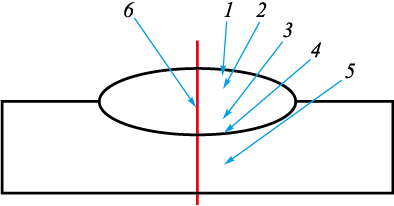
To study the microstructure, cross-sectional samples were prepared from each specimen after each surfacing mode. The preparation of the samples involved mechanical grinding, mechanical polishing on a synthetic diamond material, transitioning from coarse to fine diamond powder, and chemical etching [8; 10; 22]. The study of the structure and the measurement of the microhardness of the “coating – base metal” joint were performed on polished samples according to the scheme presented in Fig. 1.
Fig. 1. Diagram of typical connection zones for metallographic studies: |
Structural investigations were conducted using optical microscopy (OM) and atomic force microscopy (AFM) with Neophot-21 and Solver PH47-PRO microscopes, respectively [22]. Microhardness measurements were carried out using a PMT-3 microhardness tester under a load of 0.1 N.
Results and discussion
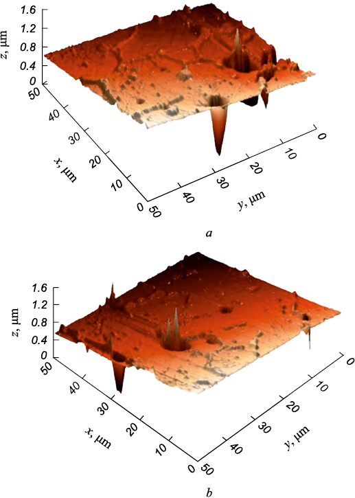
A visual inspection of the unetched crosssections from the three variants showed no macrodefects, such as pores or cracks, in the surfaced layers. However, scan images of the etched crosssections obtained with an atomic force microscope (AFM) revealed that, in all surfacing modes, rare isolated microdefects in the form of spherical pores were predominantly present at the aloyage boundary between the stainless steel and steel 20 (Fig. 2). Profilograms constructed using the sectioning method allowed for determining their morphology and size. The maximum dimensions of the micropores in the longitudinal and transverse directions were 10 and 15 µm, respectively. However, due to their small size, they are not classified as surfacing defects.
Fig. 2. Topography of defects near the alloyage boundary (AFM) |
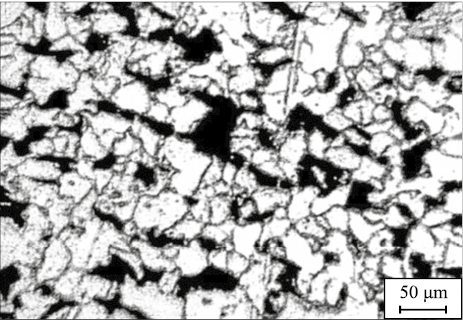
The structure of the base metal (region 5) in all cases corresponds to the structure of low-carbon steel 20 (Fig. 3), characterized by polyhedral grains of ferrite and pearlite, with an average grain size of approximately 52 µm, corresponding to a grain number of 5 to 6. The microhardness was HV0.1 = 1320 MPa.
Fig. 3. Structure of 20 steel |
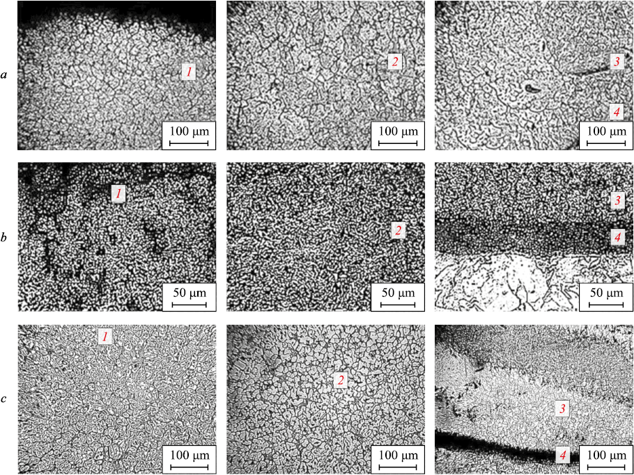
The deposited metal formed in all three surfacing variants can be conventionally divided into four regions, with the thickness of these regions varying depending on the surfacing mode. Point 4 corresponds to the aloyage boundary (the dark layer in Fig. 4) and the heat-affected zone (HAZ). In the HAZ, a Widmanstatten structure is observed adjacent to the aloyage boundary. Directly at the aloyage line, a decarburized layer with the lowest hardness (HV0.1 = 1000 MPa) was detected. The thickness of this layer in the sample processed according to variant 1 was approximately 100 µm, and in variant 2, it reached a maximum of 120 µm. In the sample surfaced using mode 3, the decarburized layer was not detected, with only small, very rare areas up to a maximum depth of 15 µm observed.
Fig. 4. Structure of deposited layer (Fig. 1), made according to option 1 – 3 (a – c): |
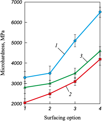
In the surfacing conducted according to variant 1, the phase composition is primarily austenite, with varying morphology and size of structural elements (Fig. 4, a). The extent of characteristic regions of the joint (ΔL) and the corresponding microhardness values are indicated in the table (measured from the upper, or free, surface of the surfacing; see the diagram in Fig. 1). In region 3, the austenite grains contain a acicular component that could not be precisely identified. Most likely, these are martensitic needles, as evidenced by the high micro-hardness values (Fig. 5): the microhardness in region 3 is nearly twice that of regions 1 and 2, reaching HV0.1 ≈ 6500 MPa. Isolated micropores were found near the boundary.
Fig. 5. Dependence of microhardness of deposited layer |
The microstructure of the deposited metal in the joint obtained using variant 2 is more homogeneous than that of the sample from variant 1 (Fig. 4, b). The microhardness changes relatively smoothly with depth, reaching its maximum only at the aloyage boundary (Fig. 5, Table). The aloyage zone (heavily etched region 4) is approximately 60 µm thick, with a hardness 1.5 times higher than the average hardness of the deposited metal, though significantly lower than in the sample surfaced using variant 1 (6500 MPa). The phase composition of the deposited metal includes austenite and fine-dispersed carbides, with a acicular component appearing near the aloyage boundary. Overall, the joint obtained using variant 2 is the most refined, free of defects such as microcracks in the deposited metal and at the aloyage boundary.
Values of microhardness in deposited layer
| |||||||||||||||||||||||||||||||||||||||||
The structure of the deposited metal surfaced using variant 3 is more homogeneous than that of the sample from variant 1 and is similar to the structure of the sample from variant 2, despite the use of two-pass surfacing here (Fig. 4, c). The microhardness in the main part of the surfacing (more than 80 %) does not significantly change with depth. In the remaining 20 % of the surfacing thickness, it increases by approximately 15 %, reaching a maximum in the boundary area (see Table). The aloyage boundary itself (heavily etched region) is about 50 µm thick, with a hardness 1.5 times higher than the average hardness of the deposited metal (Fig. 5). Overall, the joint from variant 3 has a good homogeneous microstructure, but the largest number of micropores formed in the deposited metal near the boundary.
Submerged arc surfacing (variant 1) results in a coating with a heterogeneous structure and microhardness. Isolated micropores were found in the coating near the aloyage line with the base metal. In this part of the coating, there is an increased content of quenched (acicular) structures.
Based on the macro- and microstructural analysis of the surfaced layers, it was established that the most refined structure is found in the sample processed using variant 2 – argon arc surfacing in one pass. The structure of the deposited metal consists of austenite, fine-dispersed carbides, and a acicular component near the aloyage boundary. The microhardness of the surfaced layer changes smoothly with depth, reaching maximum values only at the aloyage boundary. No microdefects were found.
The analysis of the structural-phase composition of the metal surfaced using variant 3 – argon arc surfacing in two passes – showed that the joint has a good homogeneous microstructure; however, the largest number of micropores was found in the layer surfaced during the first pass near the aloyage boundary. An increased content of acicular structures and, consequently, higher microhardness were also observed in this area.
Conclusions
The study established that during surfacing, carbon diffuses into the deposited metal, leading to the formation of carbides and the development of hardened structures, such as an acicular structure. In the heat-affected zone, a Widmanstatten structure forms, characterized by fine needles extending from ferritic plates. The base metal structure remains ferrite-pearlite.
In submerged arc surfacing, the heating rate and specific heat input are insufficient, resulting in poor mixing of the weld bath. This leads to a suboptimal structure and the formation of thermal stresses at the aloyage boundary. A similar issue arises in two-pass surfacing, where the lower layer is not fully penetrated.
References
1. Sidorov V.P., Mel’zitdinova A.V. The methodology for determining the requirements for the accuracy of welding parameters. Svarka i diagnostika. 2014;(3):10–13. (In Russ.).
2. Borisova A.L., Mits I.V., Kaida T.V., Dzykovich I.Ya., Korzhik V.N. Structure and properties of ferroborum-based electric arc coatings obtained from powder wires. Avtomaticheskaya svarka. 1991;(9(462)):66–68. (In Russ.).
3. Skoblo T.S., Tikhonov A.V., Rybalko I.N. New method for parts restoration. Avtomobil’nyi transport. 2012;(31):124–128. (In Russ.).
4. Ivashko V.S., Kurash V.V., Kudina A.V. Formation of high-quality wear-resistant metal coatings by electric arc surfacing in an ultrasonic field with introduction of a carbide powder additive into the melt. Teoriya i praktika mashinostroeniya. 2003;(2):77–81. (In Russ.).
5. Kozyrev N.A., Kibko N.V., Umanskii A.A., Titov D.A., Sokolov P.D. Improving the quality of deposited layer of rolling rolls by optimizing the composition of powder wires. Svarochnoe proizvodstvo. 2017;(7):29–34. (In Russ.).
6. Kuznetsov M.A., Zernin E.A., Kolmogorov D.E., Shlyakhova G.V., Danilov V.I. Structure, morphology and dispersion of metal deposited by arc welding with a melting electrode in argon in the presence of nanostructured modifiers. Svarka i diagnostika. 2012;(6):8–10. (In Russ.).
7. Il’yaschenko D.P., Chinakhov D.A., Danilov V.I., Schlyakhova G.V., Gotovshchik Yu.M. Physical nature of the processes in forming structures, phase and chemical compositions of medium-carbon steel welds. IOP Conference Series: Materials Science and Engineering. 2015;91:012006. http://dx.doi.org/10.1088/1757-899X/91/1/012006
8. Kuznetsov M.A., Zernin E.A., Kartsev D.S., Shlyakhova G.V., Danilov V.I. Microstructure of welded joints obtained using aluminum oxyhydroxide. Svarka i diagnostika. 2016;(4):24–26. (In Russ.).
9. Gusev A.I., Kibko N.V., Popova M.V., Kozyrev N.A., Osetkovskii I.V. Surfacing of details of mining equipment by powder wires of C – Si – Mn – Mo – V – B and C – Si – Mn – Cr – Mo – V systems. Izvestiya. Ferrous Metallurgy. 2017;60(4):318–323. (In Russ.). https://doi.org/10.17073/0368-0797-2017-4-318-323
10. Gusev A.I., Usol’tsev A.A., Kozyrev N.A., Kibko N.V., Bashchenko L.P. Development of flux-cored wire for surfacing of parts operating under conditions of wear. Izvestiya. Ferrous Metallurgy. 2018;61(11):898–906. (In Russ.). https://doi.org/10.17073/0368-0797-2018-11-898-906
11. Świerczyńska А., Varbai В., Pandey Ch., Fydrych D. Exploring the trends in flux‑cored arc welding: scientometric analysis approach. The International Journal of Advanced Manufacturing Technology. 2024;130:87–110. https://doi.org/10.1007/s00170-023-12682-6
12. Gusev A.I., Kozyrev N.A., Usoltsev A.A., Kryukov R.E., Mikhno A.R. Development of a flux-cored wire for surfacing mining equipment operating in the conditions of shock-abrasive wear. IOP Conf. Series: Earth and Environmental Science. 2018;206:012034. https://doi.org/10.1088/1755-1315/206/1/012034
13. Pańcikiewicz K. Preliminary process and microstructure examination of flux-cored wire arc additive manufactured 18Ni–12Co–4Mo–Ti maraging steel. Materials. 2021;14(21):6725. https://doi.org/10.3390/ma14216725
14. Moreno J.S, Conde F.F., Correa C.A., Barbosa L.H., da Silva E.P., Avila J., Pinto H.C. Pulsed FCAW of martensitic stainless clads onto mild steel: microstructure, hardness, and residual stresses. Materials. 2022;15(8):2715. https://doi.org/10.3390/ma15082715
15. Parshin S., Levchenko A., Wang P., Maystro A. Mathematical analysis of the influence of the flux-cored wire chemical composition on the electrical parameters and quality in the underwater wet cutting. Advances in Materials Science. 2021;21(1):77–89. https://doi.org/10.2478/adms-2021-0006
16. Cheilyakh Ya.A., Chigarev V.V. Structure and properties of deposited wear–resistant Fe–Cr–Mn steel with a controlled content of metastable austenite. Avtomaticheskaya svarka. 2011;(8):20–24. (In Russ.).
17. Mutașcu D., Karancsi O., Mitelea I., Crăciunescu C.M., Buzdugan D., Uțu I.D. Pulsed TIG cladding of a highly carbon-, chromium-, molybdenum-, niobium-, tungsten- and vanadium-alloyed flux-cored wire electrode on duplex stainless steel X2CrNiMoN 22-5-3. Materials. 2023;16(13):4557. https://doi.org/10.3390/ma16134557
18. Metlitskii V.A. Flux-cored wires for arc welding and surfacing of cast iron. Welding International. 2008;22(11): 796–800. http://dx.doi.org/10.1080/09507110802593646
19. Kejžar R., Grum J. Hardfacing of wear-resistant deposits by MAG welding with a flux-cored wire having graphite in its filling. Welding International. 2005;20(6):961–976. http://dx.doi.org/10.1081/AMP-200060424
20. Deng X.T., Fu T.L., Wang Z.D, Misra R.D.K., Wang G.D. Epsilon carbide precipitation and wear behaviour of low alloy wear resistant steels. Materials Science and Technology. 2016;32(4):320–327. http://dx.doi.org/10.1080/02670836.2015.1137410
21. Filippov M.A., Shumyakov V.I., Balin S.A., Zhilin A.S., Lehchilo V.V., Rimer G.A. Structure and wear resistance of deposited alloys based on metastable chromium – carbon austenite. Welding International. 2015;29(10):819–822. https://doi.org/10.1080/09507116.2014.986891
22. Shlyakhova G.V., Barannikova S.A., Li Yu.V., Bochkareva A.V., Zuev L.B. Study of the structure of bimetal construction carbon steel – stainless steel. Izvestiya. Ferrous Metallurgy. 2018;61(4):300–305. (In Russ.). https://doi.org/10.17073/0368-0797-2018-4-300-305
About the Authors
G. V. ShlyakhovaRussian Federation
Galina V. Shlyakhova, Cand. Sci. (Eng.), Research Associate of the Laboratory of Strength Physics
2/4 Akademicheskii Ave., Tomsk 634055, Russian Federation
V. I. Danilov
Russian Federation
Vladimir I. Danilov, Dr. Sci. (Phys.-Math.), Prof., Chief Researcher of the Laboratory of Strength Physics
2/4 Akademicheskii Ave., Tomsk 634055, Russian Federation
Review
For citations:
Shlyakhova G.V., Danilov V.I. Effect of electric arc surfacing on the structure and properties of coatings. Izvestiya. Ferrous Metallurgy. 2024;67(4):433-439. https://doi.org/10.17073/0368-0797-2024-4-433-439


