Scroll to:
Information modeling system for movement of charge layers and melt accumulation in a blast furnace well
https://doi.org/10.17073/0368-0797-2024-2-245-253
Abstract
The article presents the results of development of an information modeling system for movement of charge layers and melt accumulation in a blast furnace well. The work is based on mathematical models reflecting modern ideas on the course of physico-chemical phenomena of blast furnace melting and technological features of the blast furnace process. The use of such system makes it possible to determine and visualize the configuration of layers of iron ore materials and coke according to the working space height, taking into account a given ore load in equal-sized annular zones of the blast furnace. In constructing the configuration of the charge layers, when materials are approaching the furnace belly, the peculiarities of their movement are taken into account. This is due to the influence of tuyere zone, primary slag formation processes, and changes in thickness of the coke layer caused by development of the direct reduction process. Calculation of the melt accumulation process in the blast furnace well provides determining the volume of slag remaining there after the notch closure of previous tapping, calculating the dynamics of filling the furnace well with melts of cast iron and slag, determining the volume output of melts of cast iron and slag for the inter-tapping period and calculating the duration of tapping. The developed information modeling system makes it possible to evaluate the dynamics of changes in configuration of layers in the working space height, as well as the process of melt accumulation in the blast furnace well, using really accessible information about a working furnace. The software architecture is described, the characteristics of the modules are presented and its operation is illustrated. The developed system can be used by technological staff of a blast furnace shop to study the processes occurring in blast furnaces, improve the technological modes of operation, predict the melting progress in real time in conditions of operation instability.
Keywords
For citations:
Spirin N.A., Gurin I.A., Lavrov V.V., Zainullin L.A. Information modeling system for movement of charge layers and melt accumulation in a blast furnace well. Izvestiya. Ferrous Metallurgy. 2024;67(2):245-253. https://doi.org/10.17073/0368-0797-2024-2-245-253
Introduction
The rational distribution of charge materials in a blast furnace [1 – 3], which fully aligns with the thermal, blast, and slag parameters as well as current blast furnace practices overall [4 – 6], remains an urgent challenge for both industrial engineers and researchers studying the blast furnace process [7 ‒ 9].
The processes within the blast furnace well significantly affect its performance [10 – 12], thus drawing increased attention from engineering and technological personnel [13; 14]. The most challenging task is to arrange effective well performance, specifically the dynamics of filling the furnace hearth with cast iron and slag [15 – 19]. An information modeling system was developed to study the movement of charge layers throughout the furnace working space height and the accumulation of melt in the furnace well. This system is based on the mathematical models that reflect modern concepts of physical and chemical processes during blast furnace melting, as well as the technological features of the blast furnace process [19; 20].
Functional modeling of an information modeling system
The information system was designed using the concepts of functional modeling and the graphical notation of the IDEF0 method of structural analysis and design [21; 22]. The Federal Agency on Technical Regulating and Metrology recommends the IDEF0 methodology for constructing functional models of business and industrial engineering systems and applying them in practice. The advantage of the IDEF0 method is that IT specialists can easily exchange information with engineering personnel regarding the functioning of the software under development.
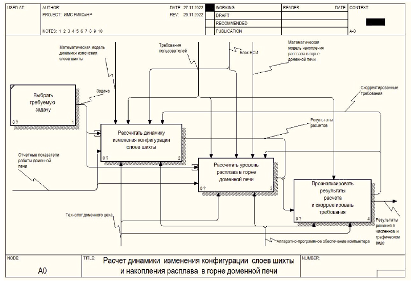
This methodology was employed to develop the functional model of the information modeling system for the movement of charge layers and melt accumulation in a blast furnace well. The model, created using Ramus software [22], contains more than 30 blocks at three levels of decomposition. It defines the main functions and relationships between individual functional blocks of the system, control activities, and mechanisms for performing each function.
Fig. 1 shows the decomposition of the first level of the functional model. The first level of decomposition of the context diagram includes four blocks: selecting the required task, calculating the dynamics of changes in the charge layers configuration, calculating the melt level in the blast furnace well, and analyzing and saving the results.
Fig. 1. Decomposition of the first level of the functional model |
Architecture of the information modeling system
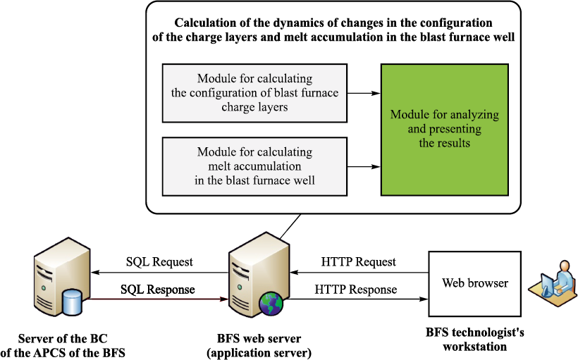
Fig. 2 shows the architecture of the developed information modeling system for the movement of charge layers and melt accumulation in the blast furnace well. The information modeling system is divided into small independent blocks – modules that functionally implement complete program segments. The idea behind this approach is that the functionality of software modules can be updated without the need to change the entire system, making it more reliable and scalable. The mathematical libraries and classes function as modules [23].
Fig. 2. Architecture of the information modeling system for movement |
The information modeling system includes the following modules:
– the module for calculating the dynamics of changes in the configuration of the blast furnace charge layers (used to calculate the configuration of the charge layers throughout the height of the blast furnace profile based on a mathematical model);
– the module for calculating the melt accumulation in the blast furnace well (used to calculate the height of slag and cast iron before the next tapping based on a given mathematical model);
– the module for analyzing and presenting the results (analyzes the results obtained from the calculation modules; displays the results in numerical and graphical forms, and can generate and export a report to a Microsoft Excel file format).
Software implementation of the information modeling system
The software implementation of the information system is based on a client-server approach, considering integration possibilities with existing company software products and data exchange via API (Application Programming Interface). The client-server architecture follows a classic three-tier structure, including presentation, application, and data levels.
The presentation level is implemented using high-level programming languages such as C#, JavaScript, HTML5, and CSS (Cascading Style Sheets). The visual design is based on Bootstrap framework. DOM (Document Object Model) objects are manipulated by the jQuery library, and plotting is handled by the Chart.js library. This level is supported by the users’ computing resources (web browsers).
The application level is implemented in C# using the ASP.NET Core MVC framework on the .NET 6 software platform [24]. ASP.NET Core framework manages pipelining of user requests, and middleware. The information system includes error handling middleware, authentication middleware, MVC middleware and session middleware.
Error handling middleware enables the system to flag issues in case of error conditions and ensures the system continues to operate and correctly display web pages, even when encountering database communication errors or executing calculation algorithms.
Authentication middleware introduces the standard ASP.NET Identity authentication and authorization mechanism and account management into the information system.
MVC middleware integrates routing systems, dependency injections, as well as model binding and data validation.
Session middleware processes temporary data of users as they interact with the system.
The data level includes a database and a software for controlling read and write access. The Microsoft SQL Server DBMS is used as the database for the system. The system communicates with the database through Entity Framework Core, which is based on Object-Relational Mapping (ORM) programming, used in object-oriented programming languages to create virtual circuits for databases. allowing data manipulation at the object or class level.
Structure of the information modeling system
The structure of the information modeling system for the movement of charge layers and melt accumulation in the blast furnace well includes the following major blocks:
1. Setting operating conditions for blast furnaces:
– setting the production rate of the blast furnace, the dimensions of its profile, and the number of tappings per day;
– setting the characteristics of the fuel-enriched blast (blast consumption, oxygen content in the blast, humidity, and natural gas consumption);
– setting the physical properties of individual charge components, specific consumption of iron ore material, and coke;
– setting the ore load in annular zones of the blast furnace;
– setting the required indicators for iron smelting (iron, manganese, silicon, and carbon content) and coke (ash, sulfur, and volatile content).
2. Calculating changes in the configuration of charge layers and melt accumulation in the blast furnace well based on mathematical models. Modeling is performed as follows [19; 20]:
2.1 ‒ calculating the parameters of equal-sized annular zones (diameter and radius) on the furnace mouth and the distance from the furnace mouth walls to the middle of each annular section;
2.2 ‒ determining the distribution of ore load in the annular zones of the furnace mouth based on the results of loading models or using indirect indicators such as the distribution of CO2 or temperature in the furnace mouth cross-section. The calculations assume that the distribution of ore load is proportional to the CO2 content and inversely proportional to the temperature distribution;
2.3 ‒ determining the configuration of layers of iron ore materials and coke in the annular sections of the blast furnace mouth, calculated for a given ore load. This involves calculating the masses and volumes of iron ore materials (IOM) and coke for each annular section, and determining the height of the layers of charge materials in the annular zones of the furnace mouth based on the volume of coke and iron ore materials and the area of the annular section;
2.4 ‒ determining the configuration of IOM and coke layers at all levels of the horizon of the furnace shaft and furnace belly.
When modeling the movement of materials in a blast furnace, it is important to consider that the stock line is shaped like a funnel towards the center of the furnace.
In this regard, the type of the formed iron ore materials (IOM) and coke layers will depend on the angle of inclination of the stock line surface, which is a variable value and included in the block of normative reference data (NRD) for the model.
Constructing the configuration of the charge layers when materials approach the furnace belly, we took into account the peculiarities of their movement caused by the impact of the tuyere zone, as well as the processes of primary slag formation that begin in the region of the belly bottom and bosh.
Reproducing the type and size of the charge layers in the region of the belly, we considered changes in the thickness of the coke layer caused by direct reduction of iron, cast iron impurities (silicon, manganese, etc.), and carbon required to carburize cast iron. Calculating the rate of charge lowering due to IOM softening in the belly, we took into account that in the zone of primary slag formation, material shrinks by approximately 20 %, which numerically equals the volume of fractional voids of the IOM layer (bed void fractions).
Above the tuyere zone, there is a rubblized region shaped as an ellipsoid of revolution [20]. The top of this zone is located in the lower part of the shaft and in the upper part of the belly. At the top of this zone, the accelerated movement of charge particles begins.
2.5 ‒ calculating the blast consumption corresponding to the furnace production rate and specific blast consumption. It should be noted that there is a difference between the estimated and actual blast consumption, which is attributed to various factors such as inevitable losses of blast moving along the air supply path and inaccuracies in recording the blast consumption.
2.6 ‒ calculating the volume of slag remaining in the furnace well after the notch closure of previous tapping;
2.7 ‒ calculating the dynamics of filling the furnace well with melts of cast iron and slag. Calculations are performed at 10 min intervals. During each 10 min interval, adjustments are made to reflect changes in the actual parameters of blast furnace melting, causing changes in the production of cast iron per unit time (blast and natural gas consumption, oxygen concentration in the blast). The thickness of the layers of cast iron and slag is then determined step by step every 10 min cumulatively, with the total height of the melts being adjusted for the volume of slag remaining in the furnace well from the previous tapping.
3. The findings are analyzed as follows:
– the dynamics of changes in IOM and coke layers are shown as these layers move towards the tuyere zones of the blast furnace;
– the dynamics of filling the furnace hearth with cast iron and slag is displayed.
The initial data is entered by an authorized user on the corresponding web pages. Then, the data from the forms is sent to the web server for validation, where the entered values are checked for correctness. If the validation is successful, the calculation is performed according to the specified calculation algorithms.
Algorithm for user interaction with the system
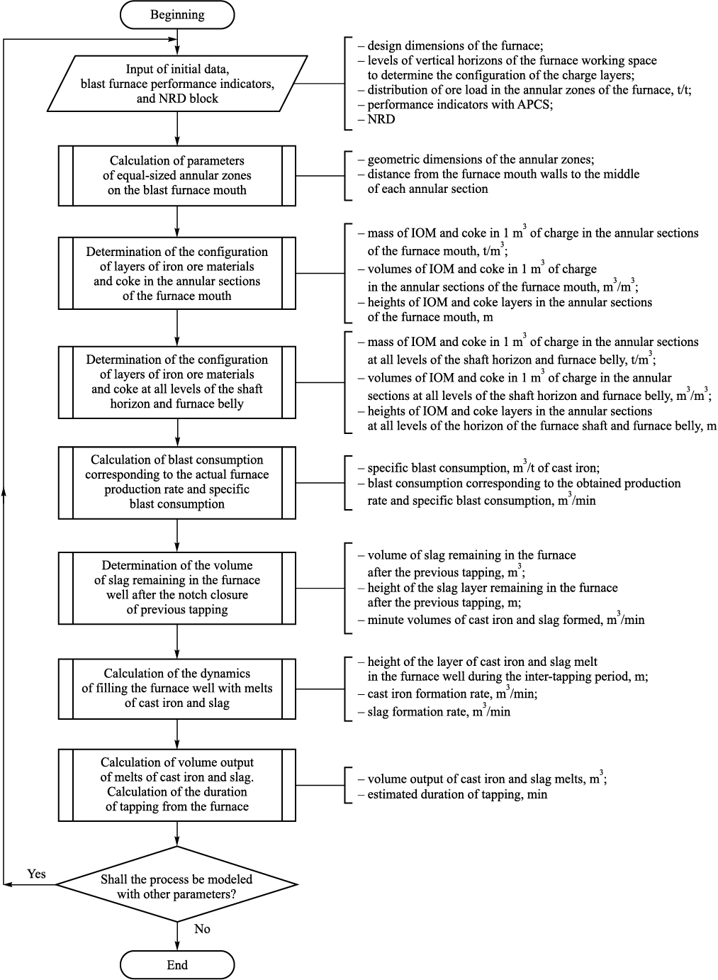
The algorithm for modeling the dynamics of changes in the configuration of the charge layers and filling of the blast furnace well as the charge moves to the tuyere zones of the blast furnace is presented in Fig. 3 and includes the following main blocks:
Fig. 3. Block diagram of the algorithm for calculating the configuration of layers |
1. Input of parameters and NRD block (ore load in annular zones, blast consumption, oxygen content in blast, humidity, natural gas flow, etc.).
2. Calculation of the parameters of equal-sized annular zones (diameter and radius of the annular zones, mass and volume of coke and iron ore material in the annular zones).
3. Calculation of the configuration of IOM and coke layers, taking into account the slope of the charge level on the furnace mouth, changes in the diameter throughout the furnace height, direct reduction processes, primary slag formation, and rubblized region above the tuyere zones.
4. Calculation of the volume minute output of slag and cast iron.
5. Calculation of the slag and cast iron layer height.
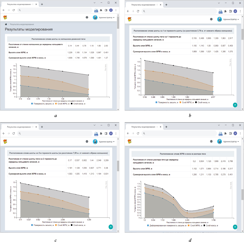
Fig. 4 presents fragments of the results of modeling changes in the configuration of IOM and coke layers on individual horizons of a blast furnace.
Fig. 4. Fragment of a web page with the results of modeling the configuration |
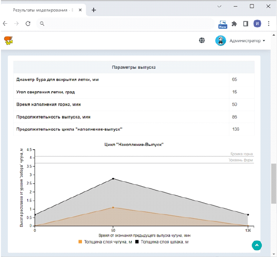
Fig. 5 shows a fragment of a web page with the results of modeling melt accumulation in a blast furnace well. The results of modeling the cycle “filling ‒ tapping” of liquid melting products in the blast furnace are presented. The tapping begins 50 min after the previous one finishes.
Fig. 5. Fragment of a web page with the results of modeling the cycle “filling ‒ tapping” |
Conclusions
We utilized modern information technologies to develop an information modeling system for the movement of charge layers and the accumulation of the melt in the blast furnace well. The system enables calculations of the dynamics of changes in the configuration of the IOM and coke layers throughout the height of the blast furnace working space, as well as the dynamics of filling the blast furnace hearth with liquid melting products.
The developed information modeling system can be used by technological staff to study the processes occurring in blast furnaces, improve the technological modes of operation, and predict the melting progress in real-time.
References
1. Sibagatullin S.K., Makhmutov R.F., Sibagatullina M.I., Starodubov V.A., Buranova E.F. On the optimal distribution of materials in the blast furnace space of the blast furnace. Teoriya i tekhnologiya metallurgicheskogo proizvodstva. 2014;(2(15)):31–34. (In Russ.).
2. Sibagatullin S.K. Formation of Charge Layer in Furnace Mouth Space. Magnitogorsk: MSTU; 2014:188. (In Russ.).
3. Tovarovskii I.G. Predictive assessment of the influence of charge materials distribution along the radius of furnace mouth on processes and indicators of blast furnace smelting. Metallurg. 2014;(8):46–52. (In Russ.).
4. Bolshakov V.I., Semenov Yu.S., Ivancha N.G., Vishnyakov V.I., Shumelchik E.I., Podkorytov A.L., Semion I.Yu., Kuznetsov A.M., Zubenko A.V. Study of the flow of burden materials and their distribution on the furnace top of a modern blast furnace. Metallurgical and Mining Industry. 2012;4(3):158–165.
5. Bol’shakov V.I., Tovarovskii I.G., Gladkov N.A., Shutylev F.M. Distribution of materials along the radius of furnace mouth and development of heat and mass transfer processes and phase transformations in the volume of a blast furnace. Ferrous Metallurgy. Bulletin of Scientific, Technical and Economic Information. 2008;(3):22–34. (In Russ.).
6. Tarasov P.V. Distribution of materials and gases around the circumference of a blast furnace. Izvestiya. Ferrous Metallurgy. 2007;50(5):17–22. (In Russ.).
7. Fojtik D., Tuma J., Faruzel P. Computer modelling of burden distribution in the blast furnace equipped by a bell-less top charging system. Ironmaking & Steelmaking. 2021;48(10):1226–1238. https://doi.org/10.1080/03019233.2021.1952829
8. Teng Z.–J., Cheng S.–S., Du P.–Y., Guo X.–B. Mathematical model of burden distribution for the bell-less top of a blast furnace. International Journal of Minerals, Metallurgy, and Materials. 2013;20(7):620–626. https://doi.org/10.1007/s12613-013-0775-7
9. Di Z., Huang M., Zhou X., Liu J., Sun J., Wang P., Wang H. The influence of central coke charging mode on the burden surface shape and distribution of a blast furnace. International Journal of Chemical Reactor Engineering. 2022;21(2): 169–179. https://doi.org/10.1515/ijcre-2022-0066
10. Bol’shakov V.I. Technology of High-Efficiency Energy-Saving Blast Furnace Smelting. Kiev: Naukova dumka; 2007:411. (In Russ.).
11. Tovarovskii I.G. Blast Furnace Smelting. Dnepropetrovsk: Porogi; 2009:768. (In Russ.).
12. Babarykin N.N. Theory and Technology of Blast Furnace Process. Magnitogorsk: MSTU; 2009:257. (In Russ.).
13. Cameron I., Sukhram M., Lefebvre K., Davenport W. Blast Furnace Ironmaking: Analysis, Control and Optimization. 1st ed. Elsevier Science; 2019:828. https://doi.org/10.1016/C2017-0-00007-1
14. Bol’shakov V.I., Murav’eva I.G., Semenov Yu.S. Forecasting the thermal condition of a blast furnace well. Stal’. 2009;(5):7–9. (In Russ.).
15. Spirin N.A., Lavrov V.V., Rybolovlev V.Yu., Gileva L.Yu., Krasnobaev A.V., Shvydkii V.S., Onorin O.P., Shchipanov K.A., Burykin A.A. Mathematical Modeling of Metallurgical Processes in Automated Process Control Systems. Yekaterinburg: UrFU; 2014:558. (In Russ.).
16. Spirin N.A., Lavrov V.V., Burykin A.A., Rybolovlev V.Yu., Krasnobaev A.V., Kosachenko I.E. Spirin N.A., Lavrov V.V., Burykin A.A., Rybolovlev V.Yu., Krasnobaev A.V., Kosachenko I.E. Model Decision Support Systems in Automated Process Control System of Blast Furnace Smelting. Yekaterinburg: UrFU; 2011:462. (In Russ.).
17. Onorin O.P., Spirin N.A., Terent’ev V.L., Gileva L.Yu., Rybolovlev V.Yu., Kosachenko I.E., Lavrov V.V., Terent’ev A.V. Computer Methods for Modeling of Blast Furnace Process. Yekaterinburg: USTU–UPI; 2005:301. (In Russ.).
18. Gordon Y., Izumskiy N., Matveienko G., Chaika O., Lebid V., Vyshinskya O. Diagnostics, optimization and mathematical models of coke-sinter-hot metal production process. AISTech 2019 – Proceedings of the Iron & Steel Technology Conf. 2019;2019-May:479–484. https://doi.org/10.33313/377/050
19. Pavlov A.V., Onorin O.P., Spirin N.A., Lavrov V.V., Gurin I.A. Some Issues of Technology, Management and Diagnostics of Blast Furnace Smelting. Yekaterinburg: Den’ RA; 2023:282. (In Russ.).
20. Onorin O.P., Spirin N.A., Lavrov V.V., Gurin I.A., Fedotov G.A. Mathematical model of the burden layers’ movement and melt accumulation in the blast furnace hearth. Stal’. 2023;(4):2–6. (In Russ.).
21. Saliy V.V., Frolov R.N., Tsebrenko K.N. Construction of economic information-analytical system for optimization of management organization. Informatsionnye resursy Rossii. 2021;(3(181)):37–40. (In Russ.). https://doi.org/10.46920/0204-3653_2021_03181_37
22. Popov A.I. Free Tools for Designing Information Systems. Moscow: Izdatel’stvo standartov; 2014;78. (In Russ.).
23. Gurin I.A., Lavrov V.V., Spirin N.A., Nikitin A.G. Web-technologies for construction of automated information-modeling systems of technological processes in metallurgy. Izvestiya. Ferrous Metallurgy. 2017;60(7):573–579. (In Russ.). https://doi.org/10.17073/0368-0797-2017-7-573-579
24. Frimen A. ASP.NET Core MVC 2 with C# Examples for Professionals. 7th ed. St. Petersburg: Dialectics LLC; 2019:1008. (In Russ.).
About the Authors
N. A. SpirinRussian Federation
Nikolai A. Spirin, Dr. Sci. (Eng.), Prof., Head of the Chair “Thermal Physics and Informatics in Metallurgy”
28 Mira Str., Yekaterinburg 620002, Russian Federation
I. A. Gurin
Russian Federation
Ivan A. Gurin, Cand. Sci. (Eng.), Assist. Prof. of the Chair “Thermal Physics and Informatics in Metallurgy”
28 Mira Str., Yekaterinburg 620002, Russian Federation
V. V. Lavrov
Russian Federation
Vladislav V. Lavrov, Dr. Sci. (Eng.), Prof. of the Chair “Thermal Physics and Informatics in Metallurgy”
28 Mira Str., Yekaterinburg 620002, Russian Federation
L. A. Zainullin
Russian Federation
Lik A. Zainullin, Dr. Sci. (Eng.), Prof. of the Chair “Thermal Physics and Informatics in Metallurgy”
28 Mira Str., Yekaterinburg 620002, Russian Federation
Review
For citations:
Spirin N.A., Gurin I.A., Lavrov V.V., Zainullin L.A. Information modeling system for movement of charge layers and melt accumulation in a blast furnace well. Izvestiya. Ferrous Metallurgy. 2024;67(2):245-253. https://doi.org/10.17073/0368-0797-2024-2-245-253


