Scroll to:
Assessment of homogeneity of ladle-furnace refining slag by calculation and experimental methods
https://doi.org/10.17073/0368-0797-2024-2-140-147
Abstract
The paper considers the issues of determining undissolved CaO and MgO particles in slags formed in a ladle-furnace unit. The assessment of slags by the presence and quantity of undissolved oxides CaO and MgO, depending on chemical composition, was carried out using a polymer model developed at UrFU and improved at IMeT UrB RAS. To determine the saturation of a multicomponent melt by CaO and MgO oxides, it is necessary to compare two parameters: thermodynamic activity of oxide in the melt, which depends on chemical composition, and saturation activity, which depends on temperature. The authors propose a method for estimating the content of undissolved particles in the slags formed at the steel ladle treatment at JSC VMZ. Most slags contain undissolved lime in an amount less than 10 %, which is sufficient for successful steel desulfurization. Theoretical calculations for determination of undissolved particles were confirmed in laboratory conditions during studies of industrial slags with a Stengelmeyer viscometer. Laboratory experiments showed the accuracy of the calculated method for determining the solid phase in the slags formed in ladle-furnace unit by comparing the viscosity changes with a decrease in the slags temperature. Solidification temperature of heterogeneous slag is 200 °C higher than that of homogeneous one. When temperature of heterogeneous slag decreased, enlarged agglomerates of solid oxides were formed, which fell under the measuring device, respectively, it showed an increased viscosity of the oxide system in the temperature range of 1570 – 590 °C. Laboratory experiments confirm the methodology for determining the solid phase in the slag.
Keywords
For citations:
Murysev V.A., Sheshukov O.Yu., Safonov V.M., Somov S.A., Metelkin A.A., Egiazar’yan D.K. Assessment of homogeneity of ladle-furnace refining slag by calculation and experimental methods. Izvestiya. Ferrous Metallurgy. 2024;67(2):140-147. https://doi.org/10.17073/0368-0797-2024-2-140-147
Introduction
Ladle metallurgy represents a crucial stage in metal processing prior to pouring into a Continuous Casting Plant (CCP). Its primary objective is to refine the liquid metal to attain the specified and uniform chemical composition, the required temperature, and a high degree of purity from non-metallic inclusions and harmful impurities [1 – 3].
Within the ladle-furnace (LF) unit of the electric furnace shop of JSC Vyksa Metallurgical Plant (JSC VMZ), highly basic and liquid-active slags are formed. The primary purpose is to remove sulfur from the metal, which can compromise the steel’s service properties. Additionally, the slag serves to protect the metal from secondary oxidation, reduce heat losses from the melt’s surface, and absorb non-metallic inclusions [1].
A key objective in the ladle treatment of steel (LTS) is to form highly basic slag to ensure maximum desulfurizing properties. This is achieved through the presence of “free” oxygen anions, originating mainly from the oxides CaO and MgO [1; 8 – 11].
Based on experience gained from refining metal at the LTS site, it is understood that successful sulfur removal requires the formation of slags saturated with CaO with a slight degree of supersaturation, not exceeding 10 %. If lime completely dissolves, there will be a deficit of CaO oxide, adversely affecting the slag’s refining properties. Conversely, if the amount of undissolved lime exceeds 10 %, it will diminish refining properties and increase consumption of slag-forming materials [1; 12].
To dissolve CaO, additives are necessary to lower its melting temperature and accelerate dissolution. Examples include fluorite (CaF2), silica-containing additives, or aluminum-containing materials.
Although fluorite (fluorspar) is widely used in steelmaking production as an efficient slag thinner, its use presents several significant drawbacks [13]:
– calcium fluoride promotes the erosion of refractory linings in steel ladles;
– at high temperatures, partial evaporation of CaF2 occurs, contributing to environmental degradation.
At modern enterprises, there is a concerted effort to replace calcium fluoride with alternative fluxing additives.
To dissolve CaO in slag, materials based on silica and alumina can be utilized. These materials form low-melting eutectics with calcium oxide, effectively reducing its melting temperature. However, the use of SiO2-based materials for refining processes is not advisable. This is due to the importance of minimizing the SiO2 content in the slag to achieve a high sulfur distribution coefficient during refining. Therefore, it is recommended to employ fluxing materials based on Al2O3 [15 – 17].
Furthermore, an evaluation of slags based on their saturation of CaO and MgO, depending on their chemical composition under the conditions of JSC VMZ, is deemed necessary.
Experimental
The evaluation of slags based on the presence and quantity of undissolved CaO and MgO oxides, depending on their chemical composition, was conducted using a polymer model (PM) developed at the Ural Federal University (UrFU) and further improved in [19].
The principle of determining the saturation of a multicomponent melt with CaO and MgO involves comparing two parameters: the thermodynamic activity of the CaO oxide in the melt (\(a_{{\rm{CaO}}}^{{\rm{td}}}\)), which depends on the chemical composition, and the saturation activity of CaO (\(a_{{\rm{CaO}}}^{{\rm{sat}}}\)), which is temperature-dependent.
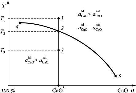
The method for determining the saturation of a melt with CaO and MgO is as follows (Fig. 1). At point 1, corresponding to temperature T1 , the inequality \(a_{{\rm{CaO}}}^{{\rm{td}}}\) < \(a_{{\rm{CaO}}}^{{\rm{sat}}}\) is valid, indicating that the melt is not saturated with CaO oxide.
Fig. 1. Method for calculating the amount of solid CaO particles in heterogeneous slag |
From point 1 to point 2 (excluding point 2 itself) \(a_{{\rm{CaO}}}^{{\rm{sat}}}\) decreases. At point 2, determined by temperature T2 , the melt becomes saturated with CaO oxide, reaching the thermodynamic activity of this oxide in the melt, i.e., the equality \(a_{{\rm{CaO}}}^{{\rm{td}}}\) = \(a_{{\rm{CaO}}}^{{\rm{sat}}}\) is valid. This condition corresponds to a certain value of СаО\(^*\) in the melt. With further decrease in temperature to T3 and a constant slag composition, excess CaO oxide will be present in the form of a solid phase, as \(a_{{\rm{CaO}}}^{{\rm{td}}}\) > \(a_{{\rm{CaO}}}^{{\rm{sat}}}\). Accordingly, the composition of the slag and the temperature at which the solid CaO phase begins to precipitate can be determined: this is line 4 – 2 – 5 (Fig. 1).
Thus, the method for determining the quantity of undissolved CaO and MgO particles and the complete composition of the liquid phase of a heterogeneous slag consists of the following steps:
1) determination of the minimum temperature at which the thermodynamic activities of CaO and MgO oxides do not exceed the saturation activities;
2) if necessary, reduction of the calculated amount of CaO and MgO oxides in the slag to satisfy the condition \(a_{{\rm{CaO}}}^{{\rm{td}}}\) = \(a_{{\rm{CaO}}}^{{\rm{sat}}}\);
3) determination of the mass fraction of undissolved CaO and MgO particles based on the component balance of the initial slag composition at a given temperature.
To validate this method, slags formed in the steel casting ladle were selected from the LTS site at JSC VMZ with known chemical compositions (Table 1).
Table 1. Chemical composition of the studied slags
| |||||||||||||||||||||||||||||||||||||||||||||
Using the proposed method and the polymer model (PM), the composition of the homogeneous phase of each slag and the quantity of the solid phase of CaO and MgO oxides were calculated (Table 2).
Table 2. Chemical composition of homogeneous phase
| ||||||||||||||||||||||||||||||||||||||||||||||||||||||||||
Slag 4 is homogeneous as it does not contain solid phases of CaO and MgO; slag 5 is heterogeneous and contains solid phases of CaO and MgO; slags 1 – 3, 6 are heterogeneous and only contain undissolved CaO oxide, the quantity of which does not exceed 10 %.
To determine the type of slags, their physical properties such as viscosity and melting temperature were compared using a laboratory unit.
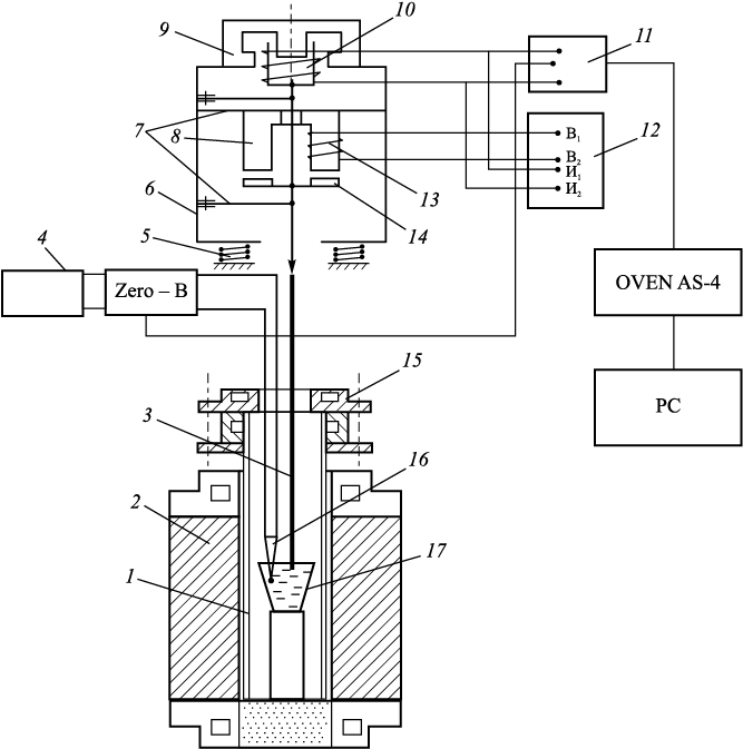
In this study, viscosity was measured using a vibrational method. The vibrational viscometer operates in resonance mode, allowing for viscosity measurements of melts within the range of 0.1 – 15 Pa·s. Its high sensitivity is attributed to operating on resonance oscillations, where the viscosity of the slag disrupts the resonance conditions. Achieving resonance requires the frequency of the current supplying the vibrator coil to match the natural frequency of the mechanical oscillations of the viscometer’s movable system. When resonance occurs, the amplitude of the movable system’s oscillations reaches maximum, inducing the maximum electromotive force in the measuring coil. The design of the vibrational viscometer used in this study was developed by Stengelmeyer [20] (refer to Fig. 2).
Fig. 2. Schematic diagram of the Stengelmeyer viscometer: |
The principle of operation is that when the probe is immersed in the slag melt, resonance oscillation is disrupted: the higher the viscosity of the slag, the smaller the amplitude of the movable system’s oscillations becomes, resulting in a smaller electromotive force in the measuring coil. Tuning the viscometer to resonance is achieved using an autogenerator. Since the measuring coil is located in the magnetic field of a ring magnet, a current is induced in it, with a frequency equal to the frequency of the oscillations of the viscometer’s movable system, i.e., a current of resonance frequency appears in it. The power of these current oscillations is increased using an amplification circuit powered by a direct current source. The amplified oscillations are then reapplied to the vibrator coil, thus automatically maintaining the resonance oscillations of the viscometer.
To prevent the transmission of vibration energy from the viscometer to the support of the micropipette manipulator, the viscometer was placed on damping springs, consisting of four pairs of spiral springs. Additionally, to ensure the stability of operation of the electrodynamic sensors, the viscometer was shielded from thermal radiation.
When measuring the viscosity of melts, a 300 mm long probe made of tungsten wire with a diameter of 1.5 mm was utilized. The probe was immersed into the flux melt to a depth of 10 mm. Immersion of the probe into the studied melt was facilitated using a micrometer screw lift, upon which the viscometer was mounted. The depth of immersion was measured using the scale of the micrometer screw lift, with the starting point (contact with the melt by the probe) being fixed using the TRM-200 meter. This was achieved by detecting the signal drop relative to the movement of the probe in the air. A digital multimeter, connected in parallel to the measuring coil, was employed for viscosity measurement, with its readings being proportional to the amplitude and frequency of the vibrations of the measuring coil. Temperature signals and the output signal of the multimeter were automatically recorded using the two-channel TRM-200 meter. The output signal of the meter, which has an RS-485 interface, was transmitted to a computer via an OVEN AC-4 automatic converter with USB/RS-485 interface and recorded in Excel spreadsheets. Signals were continuously recorded throughout the experiment with a 1 s interval.
The calibration of the viscometer was conducted on slag containing 40 wt. % CaO, 40 wt. % SiO2 , and 20 wt. % Al2O3 , where the viscosity of this slag at various temperatures is known [7]. This facilitated a “hot” calibration to be performed on slags with pre-known viscosity. The results of several calibrations were aggregated and overlaid on a single graph illustrating the dependence of viscosity on the signal obtained from the viscometer. Subsequently, an equation that most accurately described the obtained results was selected:
\[\eta = 2\left( { –6.263 + \frac{{43.088}}{{\ln E}}} \right),\]
where η is the dynamic viscosity, Pa·s; Е is the EMF recorded by the meter, mV.
The coefficients of the equation were determined by analyzing more than 20 points obtained during the calibration of the viscometer. Each point was derived by averaging 100 – 150 viscosity values during isothermal holding while simultaneously measuring the viscosity of the calibration slag. The relative error in viscosity measurement was within ±5 %.
The experimental procedure comprised the following steps:
– preparation of the slag mixture, ensuring that the volume of the prepared mixture provided a liquid slag layer thickness of at least 26 mm for a 10 mm diameter crucible with a depth of 30 – 40 mm;
– loading the prepared mixture into a molybdenum crucible and placing it in a high-temperature furnace. The mixture was heated to a temperature of approximately 1450 °C at a heating rate of approximately 9 °C/min. An inert atmosphere was maintained by introducing argon gas into the working volume of the furnace from below;
– lowering the vibration head of the viscometer, touching the surface of the slag with a tungsten probe, and immersing it to a depth of 10 mm using a micrometer screw;
– holding the sample at the specified temperature for 5 min while measuring viscosity. Data on viscosity and slag temperature were automatically recorded on a computer at 1 s intervals;
– gradual cooling of the melt at a rate of 5 °C/min; continued until the solidification of the melt, with continuous recording of the obtained data throughout the process;
– heating the melt to its melting temperature to release the end of the probe from the melt.
Experimental results
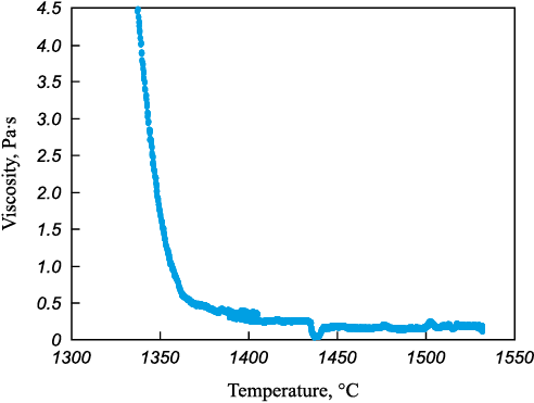
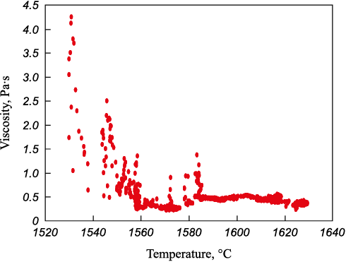
The viscosity of homogeneous and heterogeneous slags 4 and 5 was measured (Table 2). Viscosity measurements are depicted in Figs. 3 and 4.
Fig. 3. Dependence of viscosity of homogeneous slag on temperature
Fig. 4. Dependence of viscosity of heterogeneous slag on temperature |
The presented data reveal the following:
– direct viscosity measurement of heterogeneous slags presents a challenge, as significant interference is introduced into the recorded signal due to the interaction between the viscometer probe and the solid slag particles;
– heterogeneous slag exhibits increased viscosity due to the presence of solid particles in its volume, even with relatively similar chemical composition parameters;
– heterogeneous slag has an elevated crystallization temperature because the undissolved particles can act as substrates during the liquid slag crystallization process. This is manifested in a shorter crystallization interval from the onset of noticeable viscosity growth to solidification (around 20 – 30 °C for heterogeneous slag compared to 60 °C for homogeneous slag).
Slag saturated with MgO and CaO oxides exhibits increased viscosity, with its solidification temperature being 200 °C higher than that of homogeneous slag. For refining processes, it is imperative to utilize high-basicity homogeneous slag.
From the comparison of the data presented in Figs. 3 and 4, it can be deduced that heterogeneous slag possesses an elevated melting temperature. The solidification temperature of homogeneous slag falls within the range of 1350 – 1370 °C, consistent with theoretical data. In contrast, the melting temperature of the presented heterogeneous slag ranges from 1560 – 1590 °C. Additionally, it is noteworthy that as the temperature of the heterogeneous slag decreases, agglomerates of solid oxides form, contacting the measuring probe and resulting in increased viscosity of the oxide system (within the temperature range of 1570 – 1590 °С).
Analysis and discussion
At the LTS site of JSC VMZ six slag samples were selected, and the content of the solid phase of CaO and MgO oxides at a temperature of 1600 °C was determined by calculation method based on the methodology presented in Fig. 1. The following results were obtained:
– slag 4 was found to be completely homogeneous, with no solid phase present;
– slag 5 contained solid phases of CaO and MgO oxides;
– slags 1–3 and 6 contained a solid phase of CaO oxide, with the amount not exceeding 10 %.
Laboratory experiments validated the adequacy of the calculation method for determining the presence of a solid phase in slags formed in the electric arc furnace. This was achieved by comparing the viscosity changes as the temperature of slags 4 and 5 decreased. It was observed that the solidifying temperature of the heterogeneous slag was 200 °C higher, despite a relatively similar composition of the slag. Additionally, it was noted that as the temperature of the heterogeneous slag decreased, coarser agglomerates of solid oxides formed, which came into contact with the measuring probe. This resulted in an increase in the registered viscosity of the oxide system within the temperature range of 1570 – 1590 °C.
Conclusions
Recently, there has been a complete abandonment of using fluorite in steel production, aimed at enhancing efficiency and environmental safety. The addition of fluorite traditionally facilitated the quick dissolution of lime and the formation of a liquid refining slag. Consequently, ensuring optimal properties of the slag formed in the ladle furnace has become a highly relevant task. The developed method for determining the solubility limit of calcium oxide in the refining slag enables monitoring and adjustment of both the current ladle refining technology and the design of new variants.
The methodology for determining the presence of a solid phase in the slag formed in the ladle furnace was validated through laboratory experiments, where viscosity indicators of the slag were compared as the temperature decreased. It was observed that the solidification temperature of the heterogeneous slag is 200 °C higher than that of the homogeneous slag.
The calculated and experimental methods exhibited good convergence of results, with differences primarily arising in viscosity characteristics due to the presence of undissolved particles. This enables a preliminary assessment of slag properties formed in the electric arc furnace through calculation, with experimental research serving to confirm the set of slag calculations.
References
1. Bigeev A.M., Bigeev V.A. Metallurgy of Steel. Theory and Technology of Steel Melting. Magnitogorsk: MSTU; 2000:544. (In Russ.).
2. Fandrich R., Lüngen H.-B., Wuppermann C.-D. Actual review on secondary metallurgys. Revue de Metallurgie. Cahiers D’Informations Techniques. 2008;105(7–8):364–374. https://doi.org/10.1051/metal:2008053
3. Fandrich R., Luengen H.-B., Wuppermann C.-D. Secondary metallurgy – State of the art and research trends in Germany. Stahl und Eisen. 2008;128(2):45–53.
4. Cao Q., Pitts A., Nastac L. Numerical modelling of fluid flow and desulphurisation kinetics in an argon-stirred ladle furnace. Ironmaking and Steelmaking. 2018;45(3):280–287. http://doi.org/10.1080/03019233.2016.1262574
5. Shen C., Liping W., Junbo G., Yuanwang P., Fei H. Industrial investigation of decarburization and desulphurization behaviour of 120 t new single snorkel degasser. Ironmaking and Steelmaking. 2020;47(7):713–721. http://doi.org/10.1080/03019233.2019.1580029
6. Agapitov E.B., Lemeshko M.A., Sokolova M.S. Prospects for the use of hollow electrodes for deep desulfurization of steel in the ladle-furnace unit. Materials Science Forum. 2020;989:474–479. http://doi.org/10.4028/www.scientific.net/MSF.989.474
7. Komolova O.A., Grigorovich K.V. Development of LF-software for modeling of rifining processes in a ladle–furnace. Journal of Physics: Conference Series. 2019;1347:012066. http://doi.org/10.1088/1742-6596/1347/1/012066
8. Metelkin A.A., Sheshukov O.Yu., Savel’ev M.V., Shevchenko O.I., Egiazar’yan D.K. On the issue of steel desulfurization of in a ladle-furnace unit. In: Physico-Chemical Bases of Metallurgical Processes. The Int. Sci. Conf. named after Academician A.M. Samarin. Moscow: IMET RAS; 2019:77. (In Russ.).
9. Metelkin A.A., Sheshukov O.Yu., Savel’ev M.V., Shevchenko O.I., Egiazar’yan D.K. Application of ionic theory to calculate sulfide capacity of slags. Izvestiya. Ferrous Metallurgy. 2021;64(2):104–111. (In Russ.). https://doi.org/10.17073/0368-0797-2021-2-104-111
10. Savelyev M.V., Sheshukov O.Y., Egiazar’yan D.K., Metelkin A.A., Shevchenko O.I. Calculation of sulfur removal in ladle furnace unit by means of ionic theory of slags. In: IOP Conference Series: Materials Science and Engineering. 2020;966:012068. http://dx.doi.org/10.1088/1757-899X/966/1/012068
11. Sommervil’ I.D. Measurement, forecast and application of metallurgical slag tanks. In: Injection Metallurgy’ 86. Moscow: Metallurgiya; 1990:107–120. (In Russ.).
12. Yavoiskii V.I., Kryakovskii Yu.V., Grigor’ev V.P., Nechkin Yu.M., Kravchenko V.F., Borodin D.I. Metallurgy of Steel. Moscow. Metallurgiya; 1983:584. (In Russ.).
13. Metelkin A.A., Sheshukov O.Y., Nekrasov I.V., Shevchenko O.I. Improving the Durability of Lining of Ladle-Furnace Units. Nizhny Tagil: NTI (branch) UrFU; 2015;144. (In Russ.).
14. Povolotskii D.Ya. Physico-Chemical Bases of Steelmaking. Chelyabinsk: SUSU; 2006;183.
15. Socha L., Hudzieczek Z., Michalek K., Pilka V., Piegza Z. Verification of physical modelling of steel desulphurization in the plant conditions of the homogenization station. In: METAL 2014 – 23rd Int. Conf. on Metallurgy and Materials, Conference Proceedings. 2014:64–71.
16. Socha L., Bažan J., Gryc K., Morávka J., Styrnal P., Pilka V., Piegza Z. Optimisation of the slag mode in the ladle during the steel processing of secondary metallurgy. Materiali in Tehnologije. 2013;47(5):673–678.
17. Sheshukov O.Yu., Nekrasov I.V., Metelkin A.A., Lozovaya E.Yu., Shevchenko O.I., Savel’ev M.V. Modern Steel: Theory and Technology: Textbook. Nizhny Tagil: NTI (branch) UrFU; 2020:400. (In Russ.).
18. Novikov V.K., Nevidimov V.N. Polymeric Nature of Molten Slags. Yekaterinburg: UGTU – UPI; 2006:62. (In Russ.).
19. Sheshukov O.Y., Mikheenkov M.A., Nekrasov I.V., etc. Issues of Utilization of Refining Slags of Steelmaking Production. Nizhny Tagil: NTI (branch) UrFU; 2015;144. (In Russ.).
20. Shtengel’meier S.V. Electromagnetic vibration viscometer. Zavodskaya laboratoriya. 1964;(2):238–239. (In Russ.).
About the Authors
V. A. MurysevRussian Federation
Vladimir A. Murysev, Chief Specialist of the Engineering and Technology Center
45 Br. Batashevykh Str., Vyksa, Nizhny Novgorod Region 607060, Russian Federation
O. Yu. Sheshukov
Russian Federation
Oleg Yu. Sheshukov, Dr. Sci. (Eng.), Prof., Director of the Institute of New Materials and Technologies, Ural Federal University named after the first President of Russia B.N. Yeltsin; Chief Researcher of the Laboratory of Technogenic Formations Problems, Institute of Metallurgy, Ural Branch of the Russian Academy of Sciences
19 Mira Str., Yekaterinburg 620002, Russian Federation
101 Amundsena Str., Yekaterinburg 620016, Russian Federation
V. M. Safonov
Russian Federation
Vladimir M. Safonov, Dr. Sci. (Eng.), Prof. of the Chair of Electrometallurgy
206 Kalinina Str., Shimorskoe, Vyksa District, Nizhny Novgorod Region 607036, Russian Federation
S. A. Somov
Russian Federation
Sergei A. Somov, Head of the Department of the Engineering and Technology Center
45 Br. Batashevykh Str., Vyksa, Nizhny Novgorod Region 607060, Russian Federation
A. A. Metelkin
Russian Federation
Anatolii A. Metelkin, Cand. Sci. (Eng.), Assist. Prof. of the Chair of Metallurgy of Iron and Alloys of the Institute of New Materials and Technologies
19 Mira Str., Yekaterinburg 620002, Russian Federation
D. K. Egiazar’yan
Russian Federation
Denis K. Egiazar’yan, Cand. Sci. (Eng.), Assist. Prof. of the Chair of Metallurgy of Iron and Alloys of the Institute of New Materials and Technologies, Ural Federal University named after The First President of Russia B.N. Yeltsin; Senior Researcher, Head of the Laboratory of Technogenic Formations Problems, Institute of Metallurgy, Ural Branch of the Russian Academy of Sciences
19 Mira Str., Yekaterinburg 620002, Russian Federation
101 Amundsena Str., Yekaterinburg 620016, Russian Federation
Review
For citations:
Murysev V.A., Sheshukov O.Yu., Safonov V.M., Somov S.A., Metelkin A.A., Egiazar’yan D.K. Assessment of homogeneity of ladle-furnace refining slag by calculation and experimental methods. Izvestiya. Ferrous Metallurgy. 2024;67(2):140-147. https://doi.org/10.17073/0368-0797-2024-2-140-147


