Scroll to:
Investigation of performance limitations in continuous hot-dip galvanizing units associated with product defects
https://doi.org/10.17073/0368-0797-2024-1-89-105
Abstract
The goals of the work were to search and systematize the speed limits of the steel strip during hot-dip galvanizing, associated with the threat of product defects. Since speed can be combined with many other factors, this paper provides an overview of the known causes of common defects. The causes were grouped taking into account the operations of individual sections of continuous hot-dip galvanizing units. To determine the circumstances in which defects occur, a method was used that involved step-by-step stratification of retrospective data and comparison of the distribution density of influencing factors for defective and non-defective products. The method was applied in the analysis of the data on defects at the MMK Metallurgy plant in Turkey, obtained in 2020–2021. Twenty-one types of acceptable and unacceptable defects that occur during galvanizing of DX51D steel were selected for analysis. Twenty-two technological parameters were taken as factors, including the strip speed. For each selected type of the defects, a set of influencing factors is determined, and for some types of defects, the alleged causes of their occurrence are indicated. It is shown that the relationship observed for many types of defects with the strip speed can actually be caused by other factors. We determined the types of defects, the probability of which increases with an increase in the speed or the level of its change. The paper proposes measures aimed at preventing the increase in the proportion of defective products along with the performance gain.
For citations:
Ryabchikov M.Yu., Ryabchikova E.S., Novak V.S., Klimenko A.E. Investigation of performance limitations in continuous hot-dip galvanizing units associated with product defects. Izvestiya. Ferrous Metallurgy. 2024;67(1):89-105. https://doi.org/10.17073/0368-0797-2024-1-89-105
Introduction
Galvanized sheet steel is a primary product of metallurgical companies. The production from continuous hot-dip galvanizing units (CHGUs) has increased significantly in recent decades. It is reported [1] that galvanized rolled steel accounts for approximately 10 % of the global metal product consumption. In developed countries, this figure can exceed 15 %. The automotive and construction sectors are the principal consumers of these products [2].
The efficiency of CHGUs is gauged by the speed of the steel strip and downtime. The optimal speed is selected based on the specifics of the automatic control system employed at various stages of the manufacturing process. For example, in the strip heat treatment phase, when fuel usage nears maximum capacity (determined by burner capabilities), regulating the process can become challenging [3].
Research highlights the significance of human judgment in selecting the strip speed [4]. It has been found that different operators may choose varying speeds, leading to significant discrepancies in CHGU efficiency. To address this, a consulting system has been suggested to allow staff to leverage the expertise of the most effective operators. However, the impact of these choices on product quality has not been assessed. It is noted [5] that operational complexities and constraints of the continuous annealing process play a crucial role, where the human factor often reduces efficiency. Moreover, there are line speed limits associated with product quality that lack systematic organization and are typically determined through empirical means.
Typical causes of the line speed reduction
Typically, equipment is engineered for a specific maximum line speed, which may be decreased either temporarily or for extended periods. For example, a study [6] suggests utilizing line speed adjustments to rapidly modify strip temperature in response to disruptions, such as changes in the type of steel being processed or alterations in annealing temperature requirements. Short-term reductions are often implemented as a regulatory measure.
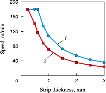
On the other hand, long-term speed reductions may stem from the limited capacity of the heating and cooling systems in the strip heat treatment sections. For example, the guidelines from the MMK Metallurgy plant provide specific line speed recommendations based on the strip’s thickness, width, and the desired temperatures at the exit of the direct heating theat , indirect heating thold , and cooling tcool stages (Fig. 1). According to these guidelines (Fig. 1), for strips thicker than 1 mm, the advised speed is considerably less than 180 m/min, which is the maximum.
Fig. 1. Recommended speeds depending on heat treatment mode: |
Enhancing the control of the continuous annealing process can lead to increased line speeds. Nevertheless, potential improvements are often constrained by defects arising from factors other than non-compliance with annealing specifications.
Classification of defects at MMK Metallurgy plant
GOST 14918 – 2020, based on ISO 3575:2016 and additional standards, outlines allowable defects based on the type, category, and classification of the coating’s finish. General acceptable defects include:
– marks from the strip and roller bends;
– scratches and abrasions that do not compromise the integrity of the coating;
– light and dead spots;
– inconsistent coloring of the passive film.
For specific types and categories of coatings, the following imperfections are permitted:
– beads, runs, buildup without cracking;
– localized roughness of the coating;
– dross pimples or inclusions;
– uneven crystallization within the coating;
– dark dots and tracks (streaks).
The presence of cracks on minor beads situated on the steel substrate’s flaws is prohibited. The standard also details unacceptable edge imperfections and establishes limits for the mass of the coating.
According to MMK Metallurgy’s data for 2020 – 2021, as illustrated in Table 1, certain defects are significantly more prevalent in defective products (Pdef ) compared to quality products (Pnorm ). The most frequent defects include uncoated areas (insufficient zinc coating and delamination) and uneven coating. Common defects of quality products are presented in Table 2.
Table 1. Common defects in rejected products
Table 2. Common acceptable defects
| ||||||||||||||||||||||||||||||||||||||||||||||||||||||||||||||||||||||||||||||||||||||||||||||||||||||||||||||||||||||||
Identified causes of defects
The occurrence of defects in the continuous hot-dip galvanizing process can be attributed to both the technological aspects of the process and the characteristics of the initial steel strip being galvanized.
Impact of steel strip properties on defect formation. The properties of the steel base can be grouped into several categories:
– structural composition of the steel;
– chemical makeup of the steel;
– mechanical characteristics;
– surface conditions, including levels of contamination [7; 8].
Research [9] points out the significant influence of steel’s chemical composition on the zinc coating’s development. Specifically, the silicon content plays a critical role. When the silicon concentration ranges between 0.06 and 0.10 %, an abnormal increase in zinc coating thickness occurs. This can result in a coating that is both fragile and possesses an unappealing gray hue. Notably, silicon content tolerances are relatively broad for many steel grades.
Further studies [10] have identified that certain marks on the coating can stem from the underlying steel’s characteristics. For instance, small ferrite grains, approximately 1 – 2 mm in diameter, emerge on the surface. Chemical analyses have detected elevated levels of Ti and Mn within these grains, alongside thin layers (up to 150 nm) of Mn and Si oxides at the juncture between the coating and the base material.
Additionally, a steel phosphorus content exceeding 0.03 % has been linked to the coating’s delamination.
According to [11], shape defects present in cold-rolled semi-finished products can directly influence the occurrence of coating defects. This is due to the abnormal effect of air knives on similar areas of the strip surface, leading to issues such as non-flatness, folds, corrugation, distortion, and scab.
Further research [8] indicates that surfaces marred by scratches, gouges, or mechanical damage exhibit significantly increased reactivity. This heightened reactivity can foster the growth of Zn – Fe crystallites as protrusions in the coating layer, resulting in areas with an excessively thick coating. Additionally, the process of galvanizing surfaces that are initially uneven is prone to result in a uneven coating thickness [12]. In attempts to counteract this, a thicker application of coating might be employed. However, such defects may still be inevitable, particularly when high zinc temperatures are involved or the immersion time in the zinc bath is extended.
The research articles [13 – 15], focusing on the development of steel for automotive body sheets, underscore the complexity of balancing a set of diverse and often conflicting requirements such as strength, ductility, formability, and corrosion resistance. The authors highlight the challenge in enhancing the steel’s strength without a comprehensive understanding of the kinetics of phase and structural transformations. For instance, it has been observed that the presence of Cr, Ni, and Cu in the steel can delay recrystallization to higher temperatures. As a remedy, it’s suggested to increase the annealing holding temperature by 30 – 50 °C to accommodate these effects.
Defects arising from the CHGU process are categorized based on the specific stages of the operation that lead to their occurrence.
Cleaning section. In the CHGU process, the steel strip is cleaned through immersion in an alkaline solution, brushed by rotating roller brushes, and subjected to electrolytic cleaning.
The primary contaminants on the strip include iron fines, oil, and dirt. As noted in the literature [8], the goal of the cleaning stage is to reduce the levels of iron fines and oil on the strip’s surface to below 20 mg/m2. The presence of fine particles in the bath can lead to reduced zinc adhesion, resulting in dross formation, material adherence issues, and uncoated sections.
Research [10] into streaky mark defects, which are long (tens of meters), narrow (up to 15 mm wide), and run parallel to the rolling direction, suggests that these marks arise from a high concentration of oxides at the interface between the coating and the steel substrate. This condition suggests that the strip surface was not adequately cleaned, leading to ineffective removal of contaminants.
Another study [16] highlights that bare spots and coating delamination primarily result from residual oil on the steel substrate. This oil, when subjected to heating in direct and indirect heating furnaces, turns into carbonaceous deposits that manifest as defects. These issues can be mitigated through effective lubricant removal and appropriate adjustment of the bath’s chemical composition.
Furthermore, the presence of uncoated cavities has been attributed to air knives failing to remove solid particles from the surface or to their inability to blow off particles that were not removed in time or were trapped, as indicated in [8].
Heating and exposure. The strip heating section in CHGU is designated for continuous recrystallization annealing. This section may consist of a furnace that utilizes indirect heating in an exothermic gas environment, or it may employ both direct and indirect heating methods. Reduction reactions occur in a protective atmosphere, aiding in the cleaning of the strip.
Research [8] indicates that inadequate management of the air/fuel mixture in the CHGU’s direct heating furnace can lead to an excessively high concentration of CO, which may result in soot accumulation on the strip. These soot deposits can cause to bare spots in the zinc coating. In the case of indirect heating furnaces, where the strip is heated in a protective atmosphere of N2 – H2 maintaining low dew points and minimal oxygen levels is crucial for enhancing strip cleanliness. Failure to control these conditions can lead to contamination issues, such as those arising from the deterioration of radiant tubes, which negatively affect the zinc coating’s adherence to the strip. Additionally, during the galvanization of low carbon steels, lubricant leaks from the hearth roll bearings can lead to surface carburization.
Moreover, it has been found [17] that when galvanizing dual-phase steels, annealing in environments with low dew points promotes significant external oxidation of trace alloying elements. This oxidation process impedes the molten zinc’s ability to reactively wet the steel surface effectively. An increase in the dew point leads to a reduction in the surface coverage of oxides.
The study [6] highlights that the thermal load in the heating section rises substantially with the increase in strip speed. This surge in thermal load amplifies the thermal crown effect of the rolls, attributed to the temperature variation within the rolls themselves, consequently heightening the likelihood of strip misalignment. Within the furnace, the strip experiences thermal buckling, a warping effect caused by uneven heat distribution, exacerbated by the strip’s diminished yield strength at elevated temperatures.
According to [18], the phenomenon of strip buckling in the furnace is primarily due to the synergistic effects of elevated temperatures and tension applied to the strip. The risk of buckling escalates as the strip widens. Achieving a more even temperature distribution across the strip’s width can mitigate buckling risks, but only within lower temperature ranges. At certain temperatures along the strip’s length, tension reaching a first critical level induces buckling. Should the tension further escalate beyond a second critical threshold, buckling might reduce, provided deformation processes have not commenced.
The literature [6; 19; 20] underscores the significant influence of the steel’s heat treatment conditions during annealing on the mechanical properties of products from CHGU. To avoid defects amid changes in production assortment or operational modes, it is advised to employ preemptive control models for strip temperature regulation [21].
Closed-circuit cooling. The closed-circuit cooling section is an integral component of the indirect heating furnace, where nitrogen-hydrogen gas serves as the cooling medium for the steel strip. This cooling process aims to reduce the strip’s temperature to near that of the molten zinc in the bath, preparing it for the galvanizing process.
Research [22] conducted on the occurrence of zinc bright edges at Sheet-rolling Shop No. 11 of PJSC Magnitogorsk Iron and Steel Works identified the root cause as the accumulation of zinc dust within the snout of the CHGU furnace’s outlet trough. This accumulation occurs when zinc dust particles evaporate from the bath and then condense on the snout, from where they subsequently fall onto the strip’s surface, leading to zinc buildup. To address this issue, modifications to the furnace outlet trough’s snout were suggested, specifically to enable dew point measurement and control within the area.
It has been observed [8] that a high strip temperature at the inlet of the zinc bath, following closed-circuit cooling, combined with a low dew point at the snout, can lead to zinc vaporization at elevated strip speeds. This vapor, upon condensing on the strip, may result in coating defects such as pimples and bulges. The significance of the strip temperature post-cooling on defect formation has also been highlighted [23]. To mitigate these issues, it is recommended [24] to minimize the temperature difference between the cooled strip and the bath. When the strip temperature exceeds 470 °C, there is an increased risk of aluminum capture in the bath, heightened dissolution of the steel strip, and accelerated dross formation.
The study documented in [17] explores how the cooling rate influences the mechanical properties of dual-phase steels.
Zinc bath. The study in [9] highlights that the formation of bottom dross in the zinc bath increases the melt’s viscosity, leading to uneven coating thickness and the appearance of bright edges. To mitigate these issues, the addition of aluminum to the bath is recommended.
Top-dross particles can become embedded in the coating if the bath’s surface oxide film adheres to the strip, as noted in [8]. This underscores the necessity of maintaining a clean bath surface. Incorrect levels of aluminum in the bath, coupled with fluctuations in the melt temperature, can escalate dross formation. The resultant dross particles may adhere to both the coating and the rolls, with larger dross particles potentially causing indentations in the strip. An excessive iron content in the bath negatively impacts the fluidity of the molten zinc, leading to a matte coating finish.
Research in [25] examines how the melt temperature within a zinc bath affects the coating thickness, demonstrating that an increase in temperature leads to thinner coatings, particularly for steels with a high silicon content.
Air knives. After the bath, the strip passes through air knives that blow excessive zinc back into the bath. This ensures the required thickness and uniformity of the coating layer.
However, as [8] reveals, air knives can induce defects such as runs and folds in the coating. Runs typically occur on thicker strips with a heavy coating, whereas ripples are more likely on thinner strips with a light coating. Factors contributing to these defects include:
– the strip’s overly smooth surface;
– elevated temperatures of either the strip or the zinc in the bath;
– excessive vibrations and the disruption of the oxide layer on the molten zinc.
The study in [26] discusses non-uniform coating issues, specifically check mark stains that create various patterns. These patterns result from differences in pressure within the air knife’s alternating vortex, with higher pressure at the edges removing more molten zinc than the lower-pressure center. The movement of these vortices, driven by jet and pressure instability, influences the pattern formation, which varies with the strip’s speed. According to [27], the characteristics of check-mark stains are affected by the initial distribution of coating thickness across the strip and the speed of the steel strip. The presence of such stains reduces the quality, productivity, and profitability of the final products [28]. Additionally, [29] demonstrates a significant drop in jet pressure at the strip’s edges compared to the peak pressure in the middle, affecting coating uniformity and leading to a thickening of the strip edge.
The studies referenced in [30; 31] delineate key variables influencing coating thickness, such as:
– strip speed;
– air knife pressure;
– height of the air knife from the bath;
– proximity of the air knife to the strip;
– opening of the gap;
– angle of air knife inclination.
Research presented in [32] highlights that deviations in coating thickness from the intended specification can often be attributed to vibrations of the strip near the air knives. These vibrations may stem from fluctuations in tension and the movement patterns of rollers within the zinc bath, suggesting that the effect of air knife settings on the quality is interlinked with strip speed and other parameters via strip vibrations. It has been observed that strip speed plays a significant role in the amplitude of vibrations near the air knife [33], with increased speeds making vibration mitigation more challenging. However, optimizing tension and controlling strip speed can limit peak vibration amplitudes. The utilization of the EMG eMASS electromagnetic strip stabilization system, as noted in [34], significantly reduces variation in coating thickness by minimizing vibration.
The authors of [11] identify severe strip vibrations, melt turbulence, and air knives clogging with the melt as causes for the appearance of zinc bright edges. They recommend adjusting the tension and strip speed to address these vibration-induced defects. Furthermore, modifications in the following areas can correct such defects:
– air knife pressure;
– proximity to the strip;
– jet angle;
– strip temperature and speed.
According to [35], when the strip exits the bath, the interaction between the molten zinc on the coating’s outer surface and atmospheric oxygen results in a more viscous top oxide layer, leading to ripple formation. This phenomenon is more pronounced with thick coatings and lower strip speeds, which can be mitigated by increasing strip speed or employing nitrogen in the air knife process.
The paper [36] explores how air knives affect the flow of liquid zinc in the bath, showing that air knife jets can significantly alter the zinc flow around the strip’s exit. This finding opens avenues for enhancing coating quality through strategic manipulation of air knife settings.
Skin pass mill and tension leveller. Following the air knives and deep cooling stages, the strip proceeds to the skin pass mill, where it undergoes rolling with a minimal elongation ratio. This process aims to maintain the steel’s drawability, enhance surface smoothness, and mitigate the zinc coating’s texture. A tension leveler is utilized to improve the strip’s flatness. It has been observed that the interaction between the hard surface of the work roll and the softer zinc coating leads to zinc transfer onto the work roll, resulting in dents on the strip’s surface during rolling.
Research [37] identifies two distinct mechanisms for the formation of coating cracks in areas of the sheet that undergo the most extensive rolling. Macrocracks emerge from the infiltration of the coating material into the metal, which subsequently embrittles the grain boundaries. Microcracks develop during the skin-pass rolling of galvanized sheets under high tangential stress conditions and at minor strip bends.
The occurrence of the “orange peel” defect during skin-pass rolling, triggered when the elongation reaches the yield strength, has also been documented. Applying the correct annealing method can alleviate this issue [38].
Combined effect of sections. Numerous studies emphasize that defects often arise from a complex interplay of factors.
Research conducted by the authors of [11] delves into the causes of zinc bright edges, highlighting that operational downtime presents a significant challenge in mitigating such defects. The solidification of zinc at the point of contact between the strip and the zinc melt complicates the operation of air knives, which are crucial for achieving a specified coating thickness.
The study [10] identifies the co-occurrence of two specific conditions as a precursor to the development of cracks on the coating surface. Initially, flaws in the technological process lead to what is described as a “wavy pattern” of defects, including voids and cracks, primarily located at the center of the coating and not directly related to the presence of steel base surface oxides. The second condition involves the nuances of skin-pass rolling, during which the coating is prone to cracking.
The paper [39] outlines two scenarios frequently leading to diminished adhesion between the zinc layer and the steel substrate. The first scenario involves:
– low temperature in the zinc bath;
– reduced temperature in the furnace’s sixth zone (the last one in the direction of metal flow);
– a sharp decrease in strip speed.
The second scenario includes:
– sudden speed alterations;
– low zinc bath temperature;
– decreased strip temperature at the furnace exit.
The researchers in [40] analyzed how various factors affect product quality, including:
– average elongation;
– strip speed;
– proximity of the air knives to the strip;
– air knife pressure.
Quality is defined by the absence of various defects, such as uneven or insufficient zinc coating due to buildup, streaks, pits, and dross inclusions. They identified specific conditions under which the incidence of defects markedly increases, namely:
– substantial elongation;
– speed over 57 m/min;
– air knife distance exceeding 1226 mm;
– elevated air knife pressure.
This analysis confirms that the strip speed plays a crucial role in the manifestation of various defects, making it challenging to simultaneously address all these aspects. Thus, identifying the root causes of defects with consideration of the line speed is crucial.
Initial data
The analysis of performance and defects at MMK Metallurgy plant was conducted through a retrospective evaluation of data from CHGU subsystem operations and product defects identified during 2020 – 2021, specifically focusing on DX51D steel. The database for this period contains detailed records for each strip roll, including the maximum, minimum, and average values of each process parameter recorded during the processing of the roll.
Effect of stoppages on defect occurrence
The research highlighted in [11] identifies downtime as a significant factor influencing the incidence of defects. Table 3 in the study details the ratio of rolls exhibiting defects that occurred during instances when the production unit was halted.
Table 3. Proportion of rolls with defects during production
|
Out of the defects examined, only three showed a probable connection to the unit’s stoppages. Among these, the defect categorized as D1 – uncoated spots – exhibited the most significant correlation with unit downtime. The analysis suggests that for the range of defects considered, unit stoppages cannot be solely attributed as the cause for most defect occurrences. Consequently, rolls that experienced unit stoppages during their processing were subsequently removed from the analysis to maintain accuracy.
The data presented in Table 4 are considered as influencing factors in this context.
Table 4. Factors explaining the causes of defects
| ||||||||||||||||||||||||||||||||||
Method determining the circumstances under which defects developed
Identifying the precise conditions leading to defects is challenging due to the multitude of process parameters that could potentially influence outcomes, along with the interconnected changes among various signals.
For each specific defect, a particular set of factors was pinpointed to enable further data stratification. This approach involved initial assessments to compare the distribution laws of each parameter for defective versus non-defective products.
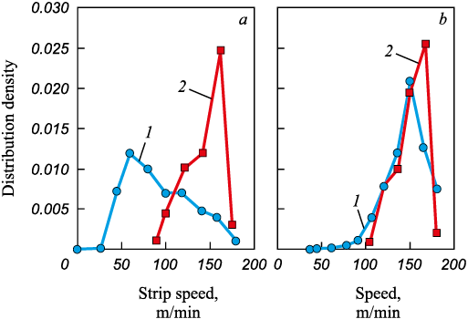
Stratification was employed to mitigate the effects of confounding factors amidst interdependent signal variations. Data were organized based on the conditions of their collection, and then analyzed within these groups separately to isolate and eliminate the influence of extraneous variables. For instance, the emergence of defect D19 was linked to changes in strip thickness and line speed. To isolate the impact of speed, data were categorized by strip thickness. Subsequently, within each defined category (stratum), the effect of speed on the occurrence of defects was examined. Fig. 2, а presents the speed distribution density for products affected by defect D19 without stratification, while Fig. 2, b shows the analysis for a specific stratum with stratification applied, indicating that the likelihood of defect occurrence is more closely related to strip thickness than to line speed.
Fig. 2. Speed distribution density for products with (2) and without (1) defect D19: |
The process of data stratification involved multiple stages. Initially, factors such as line speed and strip thickness were considered potential risk factors. Based on the outcomes of the initial analysis, these parameters were then classified as interfering factors if necessary.
Factor sets for further stratification of the data
Table 5 presents the variations in distribution density between defective and non-defective products, correlating to each defect being investigated.
Table 5. Factors that can potentially affect the occurrence of a defect
| |||||||||||||||||||||||||||||||||||||||||||||||||||||||||||||||||||||||||||||||||||||||||||||||||||||||||||||||||||||||||||||||||||||||||||||||||||||||||||||||||||||||||||||||||||||||||||||||||||||||||||||||||||||||||||||||||||||||||||||||||||||||||||||||||||||||||||||||||||||||||||||||||||||||||||||||||||||||||||||||||||||||||||||||||||||||||||||||||||||||||||||||||||||||||||||||||||||||||||||||||||||||||||||||||||||||||||||||||||||||||||||||||||||||||||||||||||||||||||||||||||||||||||||||||||||||||||||||||||||||||||||||||||||||||||||||||||||||
From the data in Table 5, it is apparent that there is no discernible link between factors F16 and F19 and any of the defects studied. Specifically, for defects D16 (Chrome stains) and D17 (Matte finish), the distribution densities of all factors for defective and non-defective products are notably similar, suggesting these factors do not significantly influence the emergence of these defects. Additionally, the pressures of the front and rear air knives (Factors F14 and F15) exhibit comparable partial distributions across all defects.
However, certain factors are identified as potentially influencing the occurrence of a broad range of defects:
– strip speed – 17 types of defects;
– strip thickness – 16 types of defects;
– strip tension – 12 types of defects;
– zinc coating thickness – 10 types of defects;
– air knife pressure – 9 types of defects;
– the minimum strip temperature after the direct heating section – 8 types of defects.
Evaluation of the impact of factors based on the results of stratification
Table 6 details the factors potentially affecting the incidence of various defects, with post-stratification analysis revealing that the relationship between defects and strip speed is often mediated by the effect of strip thickness.
Table 6. Factors affecting the occurrence of a defect
| ||||||||||||||||||||||||||||||||||||||||||||||||||||||||||||||||||||||||||||||||||
Beyond thickness, a significant array of defects can be attributed to several key factors:
– strip speed – 6 types of defects;
– air knife pressure and coating thickness – 5 types of defects;
– speed fluctuations and strip tension – 3 types of defects;
– dew point in the closed-circuit cooling section and strip temperature after this section – 2 types of defects.
Four specific defects were found to occur under conditions uniquely influenced by the distribution of strip thickness alone (D11 – abrasions, D12 – roller marks, D18 – scratches, D21 – blisters). Following strip thickness, speed emerges as the second most significant factor in the prevalence of a wide range of defect types.
Alignment of the results with the known causes of defects
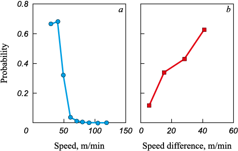
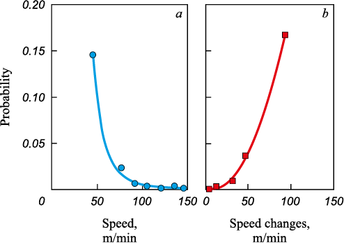
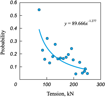
D1 – Uncoated spots. The findings indicate that variations in strip speed, in particular, are a probable cause of uncoated spots (Fig. 3). This observation aligns with the insights from [39], highlighting the impact of speed changes on this type of defect. Nevertheless, only a minor portion of such defects can be attributed to unit stoppages, suggesting that uncoated spots are not directly linked to the unit’s cessation of operation. The connection with tension suggests that these defects are likely due to mechanical factors. Contrary to the issues discussed in [8; 17], no significant effect from either high or low dew point values in the indirect-heating furnace on this type of defect was detected.
Fig. 3. Dependence of probability of uncoated spots (D1) on: |
D2 – Uneven coating. The findings align with observations from [12], indicating that an elevated melt temperature complicates the achievement of a thick, uniform coating (Fig. 4). A higher melt temperature correlates with increased metal throughput in CHGU, presenting challenges in temperature control. This defect [41], adversely impacts the surface’s wetting properties could be attributed to the diffusion of iron through the inhibitory Fe – Al interfacial layer, which, as reported in inhibiting Fe – Al interfacial layer, which, according to [41], negatively affects the surface wetting. When the aluminum content in the bath is at 0.2 %, the formation of the inhibiting layer is complete, provided the strip temperature at the bath inlet is between 440 to 480 °C. Nonetheless [24] points out that the diffusion of iron through this inhibiting layer escalates as temperatures increase, recommending that strip temperatures should not surpass 470 °C. Given that aluminum content in the melt up to 0.3 % significantly influences the duration until Fe – Zn phases develop in a non-linear manner, the depletion of aluminum content in the bath, coupled with elevated temperatures of both the strip and the melt, may lead to the emergence of defects.
Fig. 4. Dependence of probability of obtaining an uneven coating (D2) on: |
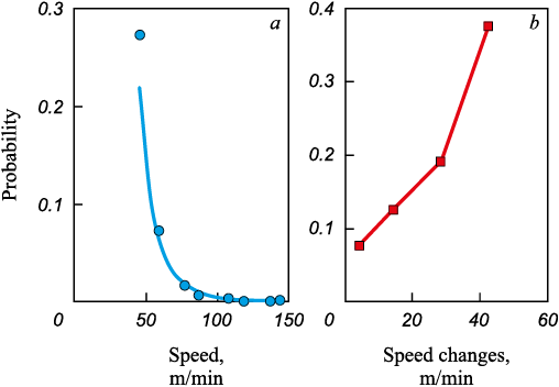
D3, D4 – Damage marks, Dents. Defects in rolled products are commonly the result of mechanical damage. The findings imply that such damage can happen directly on the CHGU line, especially when there are abrupt changes in speed (Fig. 5, 6). The observation of a high dew point in products exhibiting dents leads to the suggestion that these defects may be due to contamination. Specifically, as mentioned in [8], dross particles in the bath can lead to the formation of dents on the rolled products.
Fig. 5. Dependences of tail marks probability (D3) on:
Fig. 6. Dependences of probability of imprints (D4) on: |
D5 – Rough edges. Typical edge irregularities such as scab, corrugation, and ripple effect are linked to the characteristics of the original strip. The connection between these irregularities and factors like coating thickness and air knife pressure remains ambiguous.
D6 – Coating thickness defects. It is postulated that as the strip temperature at the bath inlet increases, the absorption of aluminum from the bath also rises. This, as [24] suggests, can make the melt more viscous under similar conditions, potentially leading to inconsistencies in coating thickness, as [9] indicates.
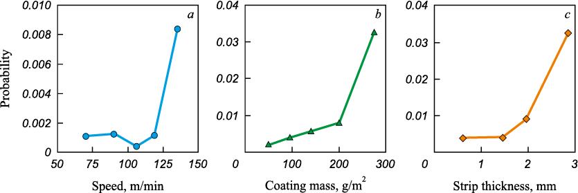
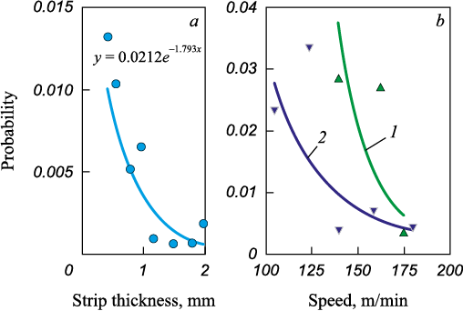
D7 – Macroinclusions. According to [8], these defects may result from the strip capturing dross particles alongside the oxide film on the surface of the zinc bath, with a thicker coating more likely to retain larger dross particles (Fig. 7, b). It is theorized, based on [36], that lower air knife pressure has a diminished impact on the bath’s melt near the strip’s exit, where the oxide film forms and gets entrapped. An increase in strip temperature at the bath inlet could facilitate the melt’s contamination with zinc oxides. A thicker strip and strip speeds surpassing 125 m/min are believed to heighten the risk of this defect (Fig. 7, а, c). This phenomenon could be attributed to the dynamics of the melt and a greater influx of dross particles into the region where they are trapped.
Fig. 7. Dependence of probability of macroinclusions (D7) on: |
D8 – Non-conforming mechanical properties. The temperature distribution of the strip at the outlets of direct and indirect heating furnaces shows variations between defective and non-defective products. However, the limited amount of data complicates the verification of this difference through stratification. Given that this type of defect is not visible to the eye, adherence to the steel heat treatment protocol is imperative.
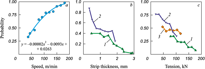
D9 – Zinc bright edges. Fig. 8, а illustrates the likelihood of defect occurrence in relation to strip speed for strips approximately 0.5 mm thick, indicating a decrease in defect probability with a reduction in speed. It has been determined that the occurrence of defects is dependent on strip thickness (Fig. 8, b) only at speeds below 90 m/min, while at higher speeds, the chance of defects occurring remains relatively unchanged. Low air knife pressure (indicative of low melt viscosity) influences defect formation predominantly at lower speeds for thicker strips, particularly at the initial stages of defect development. Increasing the tension at the inlet of the skin-pass section (Fig. 8, c) lowers the probability of defects, suggesting that vibration might contribute to the formation of bright edges.
Fig. 8. Dependence of probability of bright edges (D9) on: |
D10 – Rough coating. The defect impacts the protective qualities, wear resistance, and visual appeal of the galvanized strip, typically originating from the properties of the initial strip. The roughness of the base strip appears to correlate with its thickness. However, the reasons behind tension differences between defective and non-defective products remain ambiguous.
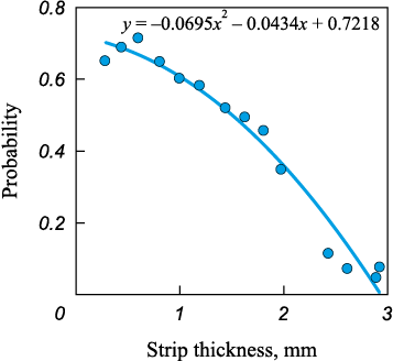
D11, D12 – Abrasions and roller marks. Abrasions are solely associated with thickness, aligning with findings from [10] that attribute the original strip’s properties as the root cause of this defect. The occurrence of abrasions consistently diminishes as the thickness increases (Fig. 9). The probability of encountering roller marks ranges between 0.25 and 0.30 for most thicknesses, but the defect is virtually absent in strips thinner than 1 mm, with the underlying causes yet to be elucidated.
Fig. 9. Dependence of probability of abrasions (D11) on hmet |
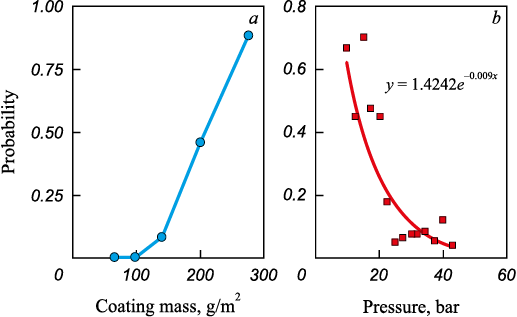
D13 – Wavelike coating. The likelihood of defects escalates with an increase in coating thickness, irrespective of the strip’s thickness (Fig. 10, a). This observation aligns with findings from [35]. Conversely, a higher speed diminishes the probability of defects, but only for thinner coatings (up to 140 g/m2), where defects emerge under reduced air knife pressure (Fig. 10, b). Thus, low melt viscosity with thin coatings may lead to a wavelike pattern on the coating.
Fig. 10. Dependence of probability of D13 defect on: |
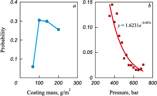
D14 – Marks related to skin-pass rolling. It is suggested by [8] that such marks result from the coating adhering to the rollers. The defect manifests when the coating mass is above 80 g/m2 (Fig. 11, а). At the coating mass of 80 – 140 g/m2, defects appear under diminished knife pressure (Fig. 11, b), with the wavelike coating potentially leading to sticking.
Fig. 11. Dependence of probability of D14 defect on: |
D15 – Dark streaks. According to [10], presence of oxides at the interface between the coating and steel is a contributing factor to the defect, although the connection between oxide formation, strip thickness, and temperature remains uncertain.
D18 – Scratches. Scratches are attributed to three potential sources:
– scratches on the original strip;
– the strip sagging educing friction with rollers, commonly in the zinc bath;
– dross sticking to the roller in the zinc bath.
It was discovered that the risk of scratches significantly increases when the strip thickness is over 2 mm. In analyzing this defect, the tension of the strip in various sections was considered as factor F20. For strips thicker than 2 mm, the defect probability diminishes as tension at the skin pass section’s inlet increases (Fig. 12).
Fig. 12. Dependence of probability of D18 defect |
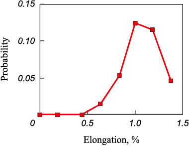
D19 – Orange peel. The occurrence of the defect is notably prevalent on thin strips that experience a significant reduction in dew point within the closed-circuit cooling section. This observation aligns with findings from [8], which link the formation of pimples to zinc evaporation prompted by a low dew point at the snout. The defect is most likely to manifest at approximately 1 % elongation (Fig. 13), corroborating the insights provided in [38].
Fig. 13. Dependence of probability of D19 defect on extension |
D20 – Cracks. Such defects could originate from cracks in the original strip or internal stresses within the steel that annealing failed to resolve. Given the lack of correlation with annealing parameters, it’s plausible to associate these defects with pre-existing cracks in the strip, a hypothesis supported by the marked variability in defect probability across different strip thicknesses and the observation that the issue is more pronounced with thicker coatings.
D21 – Blisters. Blisters may be linked to hydrogen absorbed during the etching process and released during galvanizing. Alternatively, they could result from dross particles becoming entrapped when the bath’s bottom dross layer is disturbed. The absence of a relationship with coating thickness suggests the latter explanation might be more accurate. The dependencies on strip thickness (Fig. 14, а) and line speed (Fig. 14, b) could reflect the dynamics of strip movement within the zinc bath.
Fig. 14. Dependence of probability of D21 effect on: |
Types of defects that limit performance
The potential for enhancing the CHGU performance is primarily linked to increasing the processing speed of common-grade steel strips. Fig. 2 demonstrates that only the thinnest strips, with thicknesses up to 0.4 mm, are currently processed at the unit’s maximum speed. However, these constitute just 4 % of the DX51D steel strip rolls. In contrast, approximately 60 % of the rolls have a strip thickness over 1 mm, indicating a significant opportunity to boost processing speeds for these thicker strips.
Considering this, it’s possible to pinpoint defects that become more prevalent with increased speeds and could constrain performance even when heat treatment standards are adhered to:
– D2 – Uneven coating;
– D7 – Macroinclusions;
– D9 – Zinc bright edges.
The presence of an uneven coating restricts the ability to raise processing speeds. Findings suggest that the likelihood of this defect could be diminished by more accurately controlling the melt temperature in the zinc bath, achieved by reducing the temperature disparity between the strip after closed-circuit cooling and the melt.
Macroinclusions represent another frequent defect, with their occurrence spiking notably as strip speeds surpass 125 m/min. The current operational parameters allow for processing strips thinner than 1 mm at such speeds, leaving uncertain the impact of increased speeds on thicker strips in terms of defect prevalence.
At exceedingly high speeds, the emergence of zinc bright edges on processed strips becomes inevitable, although this limitation might be less significant since bright edges are often deemed an acceptable defect. Optimizing the design of air knives could potentially address this issue.
Moreover, a rise in the speed may also increase the chances of encountering defects not extensively studied due to their rarity or limited data available. As noted in [6], an escalation in strip speed may induce corrugation in the strip.
Experimenting with different strip speeds to optimize current performance can lead to substantial and frequent single speed adjustments. However, such changes in speed significantly influence the likelihood of several defects:
– D1 – Uncoated spots;
– D3 – Damage marks;
– D4 – Dents.
The analysis identified similar patterns in how speed and its fluctuations affect the emergence of these three defects, suggesting they may share a common cause related to tension control amid changes in strip speed. Dents exhibit the least sensitivity to speed variations, with a high probability of occurrence only when speed alterations exceed 50 m/min. The chance of all three types of defects occurring diminishes to a minimal level as the speed increases.
Conclusions
The findings indicate that enhancing the control over the temperature and chemical composition of the melt in the zinc bath, along with the temperature of the strip following the closed-circuit cooling section, is essential for increasing strip speed and, thereby, overall performance. Given that defects arising from frequent changes in strip speed are deemed unacceptable, there is a clear need to scrutinize and potentially refine the strip tension control systems across various sections of the unit.
References
1. Subbotina Yu.M., Radionova L.V. Technological features of continuous lines for hot-dip galvanizing of a steel strip. Bulletin of the South Ural State University. Ser. Metallurgy. 2016;16(1):112–119. (In Russ.). https://doi.org/10.14529/met160116
2. Nikiforov B.A., Salganik V.M., Denisov S.V., Stekanov P.A. Commercial production of high-strength rolled products at MMK JSC for the automotive industry. Vestnik of Nosov Magnitogorsk State Technical University. 2006;4(16):41–45. (In Russ.).
3. Ryabchikov M.Yu., Ryabchikova E.S., Kokorin I.D. System of temperature stabilization in a heating furnace based on sliding mode control and fuzzy logic. Mekhatronika, Avtomatizatsiya, Upravlenie. 2020;21(3):143–157. (In Russ.). https://doi.org/10.17587/mau.21.143-157
4. Antonenko O. How did we find out that one of the galvanizing teams worked faster than the others and what happened next. Available at URL: https://habr.com/ru/company/nlmk/blog/589267/ (Accessed: 30.04.2023). (In Russ.).
5. Sahay S.S., Kapur P.C. Model based scheduling of a continuous annealing furnace. Ironmaking and Steelmaking. 2007;34(3):262–268. https://doi.org/10.1179/174328107X165708
6. Yahiro K., Shigemori H., Hirohata K. Development of strip temperature control system for a continuous annealing line. Proceedings of IECON ‘93 – 19th Annual Conf. of IEEE Industrial Electronics. 2002:481–486. https://doi.org/10.1109/IECON.1993.339029
7. Mezin I.Yu., Zotov S.V., Kramzina L.V. Analysis and increase of quality of zinc coating on wire for automobiles. Kachestvo v obrabotke materialov. 2017;(1(7)):14–18. (In Russ.).
8. Saravanan P., Srikanth S. Surface defects and their control in hot dip galvanized and galvannealed sheets. International Journal of Advanced Research in Chemical Science (IJARCS). 2018;5(11):11–23.
9. Radionova L.V., Subbotina Yu.M. Advantages and shortcomings of hot dip galvanizing steel sheet. Galvanizing problems. Russian Internet Journal of Industrial Engineering. 2013;(2):3–9. (In Russ.).
10. Hong M.-H., Saka H. FIB and TEM observations of defects in hot-dip zinc coatings. Journal of Electron Microscopy. 2004;53(5):545–552. https://doi.org/10.1093/jmicro/dfh053
11. Berezhnaya G.A., Zarutskaya A.O., Karimova D.Yu. Quality analysis of hot-dip galvanized strip produced at plate rolling mill no 11 at MMK OJSC. Kachestvo v obrabotke materialov. 2016;(2(6)):39–42. (In Russ.).
12. İlhami Pektaş. Galvani̇z hatalari ve çözüm öneri̇leri̇. Ankara; 2020:76. (In Turk.).
13. Rodionova I.G., Uglov V.A., Zaitsev A.I., Protasov A.V., Mishnev P.A., Adigamov R.R., Pavlov S.I., Las’kov S.A., Nikolaev O.A., Kiryushin A.A., Tikhonov A.K., Ryabchikov V.G. A new generation of economical automotive steel. Steel in Translation. 2016;46(1):65–73. https://doi.org/10.3103/S0967091216010125
14. Zaitsev A.I., Koldaev A.V., Rodionova I.G., Stepanov A.B. A modern approach to improving the complex properties of automotive sheet and other types of steels. In: Scientific and Technological Progress in Ferrous Metallurgy – 2019. Materials of the IV Int. Sci. Conf. 2019:66–72. (In Russ.).
15. Tikhonov A.K., Rodionova I.G. Thermomechanical treatment in the recrystallizational annealing of automotive cold-rolled steel. Steel in Translation. 2022;52:451–459. https://doi.org/10.3103/S0967091222040143
16. Srikanth S., Sharma C.B., Bhattacharyya A., Amitava Ray. Metallurgical investigations into genesis of bare spots, exfoliation, and matte coating appearance in hot dip galvanized steel sheets. JFAPBC. 2005;(3):73–81. https://doi.org/10.1361/15477020523509
17. Liu H., Li F., Shi W., Swaminathan S., He Y., Rohwerder M., Li L. Challenges in hot-dip galvanizing of high strength dual phase steel: Surface selective oxidation and mechanical property degradation. Surface & Coatings Technology. 2012;206(16):3428–3436. https://doi.org/10.1016/j.surfcoat.2012.02.001
18. Luo H., Dunbar W.S., Moore J.E. Buckling analysis of a heated steel strip in a continuous annealing furnace. Journal of Manufacturing Science and Engineering. 1999;121(1): 76–83. https://doi.org/10.1115/1.2830578
19. Wu H., Speets R., Ozcan G., Ekhart R., Heijke R., Nederlof C., Boeder C.J. Non-linear model predictive control to improve transient production of a hot dip galvanising line. Ironmaking & Steelmaking. 2016;43(7):541–549. https://doi.org/10.1080/03019233.2015.1126687
20. Ryabchikov M.Yu. Selection of steel strip annealing energy-saving conditions in view of the substandard products share. Journal of Chemical Technology and Metallurgy. 2020;55(1):182–191.
21. Ryabchikov M.Yu., Ryabchikova E.S., Novak V.S. Hybrid model for metal temperature control during hot dip galvanizing of steel strip. Mekhatronika, Avtomatizatsiya, Upravlenie. 2023;24(8):421–432. (In Russ.). https://doi.org/10.17587/mau.24.421-432
22. Kleshcheva S.E., Kasatkina E.G. Analysis of the quality level of galvanized metal in the sheet-rolling shop No. 11 of the PJSC “MMK”. Kachestvo v obrabotke materialov. 2019;(1(11)):18–23. (In Russ.).
23. Ryabchikov M.Yu., Ryabchikova E.S., Shmanev D.E., Kokorin I.D. Strip cooling control for flexible production of galvanized flat steel. Izvestiya. Ferrous Metallurgy. 2021;64(7):519–529. (In Russ.). https://doi.org/10.17073/0368-0797-2021-7-519-529
24. Sawaitul P.B., Chowriwar S.A., Lade I.P. Minimization of dross formation during the continuous galvanizing process in the steel industry. International Journal of Emerging Technology and Advanced Engineering. 2012;2(1):45–51.
25. Bondareva O.S., Mel’nikov A.A. Influence of the temperature of a zinc melt on the coating thickness and structure during high-temperature zincplating steels with a high silicon content. Powder Metallurgy аnd Functional Coatings. 2015;(1):66–70. (In Russ.). https://doi.org/10.17073/1997-308X-2015-1-66-70
26. Yoon H.G., Ahn G.J., Chung M.K., Kim J.K. Aerodynamic investigation of air knife system to find out the mechanism of the check mark in a continuous hot-dip galvanizing process. Proceedings of IMECE2008 2008 ASME Int. Mechanical Engineering Congress and Exposition. 2008:1–7. https://doi.org/10.1115/IMECE2008-68056
27. Hongyun S., Gi Y.H., Kyoon C.M. CFD analysis of sag line formation on the zinc-coated steel strip after the gas-jet wiping in the continuous hot-dip galvanizing process. ISIJ International. 2011;51(1):115–123. https://doi.org/10.2355/isijinternational.51.115
28. Gi Y.H., Kyoon C.M. Development of novel air-knife system to prevent check-mark stain on galvanized strip surface. ISIJ International. 2010;50(5):752–759. https://doi.org/10.2355/isijinternational.50.752
29. Bao C., Kang Y., Li Y. Numerical analysis of edge over coating and baffle effect on hot-dip galvanizing. Surface Review and Letters. 2017;24(1):1750010. https://doi.org/10.1142/S0218625X1750010X
30. Mao K., Yang Y.-L., Huang Z., Yang D.-y. Coating thickness modeling and prediction for hot-dip galvanized steel strip based on GA-BP neural network. 2020 Chinese Control and Decision Conf. (CCDC 2020). 2020;3484–3489. https://doi.org/10.1109/CCDC49329.2020.9164854
31. Zhang Y., Cui Q.-p., Shao F.-q., Wang J.-s., Zhao H.-y. Influence of air-knife wiping on coating thickness in hot-dip galvanizing. Journal of Iron and Steel Research International. 2012;19(6):70–78. https://doi.org/10.1016/S1006-706X(12)60130-7
32. Xu P., Wang B., Ye J., Zhang H., Huang Z., Xu X. Research on the vibration of sheet metal near the zinc pot area in continuous hot-dip galvanizing line. Applied Mechanics and Materials. 2012;141:471–477. https://doi.org/10.4028/www.scientific.net/AMM.141.471
33. Li J., Yan Y.-H., Guo X.-H., Wang Y.-Q. Research on vibration control method of steel strip for a continuous hot-dip galvanizing line. ISIJ International. 2012;52(6):1072–1079. https://doi.org/10.2355/isijinternational.52.1072
34. Dombrowski S., Pereira A. Electromagnetic strip stabilization: EMG-EMASS® – technology, results, customer experiences, and future development. 50º Seminário de Laminação. 2013:252–260.
35. Rajiv E.P., Jain N.C., Mahakalkar Nilesh, Pawar B.D. Defects in continuous hot dip galvanized steel sheet and their remedies. URL: http://samoseyindia.in/web-english/galvn1.html (accessed: 30.04.2023)
36. Yuan S., Zhou X., Huang Y., Yang P. Influence of air knives on liquid zinc flow in galvanising bath. Ironmaking & Steelmaking. 2016;43(2):83–87. https://doi.org/10.1179/1743281215Y.0000000051
37. Belov V.K., Krivko O.V., Gubarev E.V., Demchuk F.A., Pogonin E.Yu., Samorodova E.G. Identification of causes of coating dusting during stamping of parts from hot-dip galvanized sheet. Aktual’nye problemy sovremennoi nauki, tekhniki i obrazovaniya. 2021;12(1):99–103. (In Russ.).
38. Wang L., Tang D., Liu X., Zhang Y., Zhou S. Analysis of orange peel defects on hot-dip galvanized high strength low alloy steel. Advanced Materials Research. 2014;1004–1005:221–226. https://doi.org/10.4028/www.scientific.net/AMR.1004-1005.221
39. Martínez-de-Pisón F.J., Sanz A., Martínez-de-Pisón E., Jiménez E., Conti D. Mining association rules from time series to explain failures in a hot-dip galvanizing steel line. Computers & Industrial Engineering. 2012;63(1):22–36. https://doi.org/10.1016/j.cie.2012.01.013
40. Colla V., Matarese N., Cervigni F. Quality improvement in hot dip galvanizing line through hybrid case-based reasoning system. UKSim 15th Int. Conf. on Computer Modelling and Simulation. 2013:161–166. https://doi.org/10.1109/UKSim.2013.24
41. Yang H., Zhang S., Li J., Liu X., Wang H. Effect of strip entry temperature on the formation of interfacial layer during hot-dip galvanizing of press-hardened steel. Surface & Coatings Technology. 2014;240:269–274. http://dx.doi.org/10.1016/j.surfcoat.2013.12.040
About the Authors
M. Yu. RyabchikovRussian Federation
Mikhail Yu. Ryabchikov, Cand. Sci. (Eng.), Assist. Prof. of the Chair of Automated Control Systems
38 Lenina Ave., Magnitogorsk, Chelyabinsk Region 455000, Russian Federation
E. S. Ryabchikova
Russian Federation
Elena S. Ryabchikova, Cand. Sci. (Eng.), Assist. Prof. of the Chair of Automated Control Systems
38 Lenina Ave., Magnitogorsk, Chelyabinsk Region 455000, Russian Federation
V. S. Novak
Russian Federation
Vladimir S. Novak, Bachelor of the Chair of Automated Control Systems
38 Lenina Ave., Magnitogorsk, Chelyabinsk Region 455000, Russian Federation
A. E. Klimenko
Russian Federation
Aleksandr E. Klimenko, Master Student of the Chair of Automated Control Systems
38 Lenina Ave., Magnitogorsk, Chelyabinsk Region 455000, Russian Federation
Review
For citations:
Ryabchikov M.Yu., Ryabchikova E.S., Novak V.S., Klimenko A.E. Investigation of performance limitations in continuous hot-dip galvanizing units associated with product defects. Izvestiya. Ferrous Metallurgy. 2024;67(1):89-105. https://doi.org/10.17073/0368-0797-2024-1-89-105


