Scroll to:
Modeling the pattern of metal flow during forming of forgings from a flat billet
https://doi.org/10.17073/0368-0797-2023-6-768-774
Abstract
Parts made of the billets with a thin web and stiffeners are manufactured at metallurgical enterprises in special workshops equipped with powerful hydraulic presses. Often their production is accompanied by the defects that worsen the product macrostructure. In this regard, new techniques are relevant that allow modeling the processes of forming of forgings with stiffeners. The processes of metal treatment by pressure are difficult to create a mathematical model describing the stress-strain state of plastic forming of metal. One of the ways to solve the problem of modeling the pattern of metal flow and the spatial diagram of contact pressures is the “theory of thin layer flow”, based on assumptions that simplify the initial system of differential equations. Then the problem is reduced to a purely geometric one and can be solved within the framework of the “sandy analogy” using the proposed methodology. The paper presents the results of computer and physical modeling of the forming of stamped forgings with contour stiffeners. The experiment was carried out in industrial conditions on the precipitation of flat billets made of AK6 alloy on a hydraulic press with a deformation force of 150 MN. It is shown that the proposed software package can have a different functional purpose: express analysis of the pattern of metal flow and calculation of the shape of the billet at the stages of its deformation. This allows, by sorting through values of the geometric parameters of the stamp engraving, to obtain different patterns of metal flow and profiles of stiffeners and choose from them those that guarantee the most uniform filling of the stamp cavities with metal under the stiffeners, which ensures defect-free production of the product.
For citations:
Solomonov K.N., Tishchuk L.I., Gorbatyuk S.M., Snitko S.A., Chicheneva O.N. Modeling the pattern of metal flow during forming of forgings from a flat billet. Izvestiya. Ferrous Metallurgy. 2023;66(6):768-774. https://doi.org/10.17073/0368-0797-2023-6-768-774
Introduction
Improving the production efficiency of the domestic industry [1 – 4], heavy engineering in particular [5 – 8], is an urgent concern. Parts composed of billets with thin webs and stiffeners are typically manufactured at metallurgical plants in specialized workshops equipped with high-capacity hydraulic presses. However, their production often encounters defects that degrade the macrostructure of the final product. Hence, novel methods enabling the modeling of the forging processes involving stiffeners are highly relevant. The method devised by the authors could also be effectively applied in the fabrication of rail wheel billets. In the production of forged-rolled rail wheels, a critical operational step involves obtaining billets with minimal asymmetry across all units of the press-rolling line [9; 10 – 13]. This aspect is contingent upon various factors, primarily the stability of the mass and dimensions of the initial billets [14 – 18].
In metal forming processes, creating a mathematical model to describe the stress-strain state of plastic metal forming poses significant challenges. One approach to address this modeling issue concerning the metal flow pattern and the spatial distribution of contact pressures is through the “theory of thin layer flow” [19]. This theory relies on assumptions that simplify the initial system of differential equations, transforming the problem into a purely geometric one. Subsequently, it can be resolved within the context of a “sandy analogy” method developed by the authors [20].
Main principles of the developed method
The developed method is founded on the following principles [21; 22].
The shortest-normal principle governs the direction of current lines perpendicular to the forging contour, which represents a line of abrupt changes in the layer thickness (incorporating stiffeners or elevations along the forging web). During the initial stage of strain, when the terminal pressures are uniform along the contour, the metal flows orthogonally to the contour, and the quantity of leaked metal at each boundary point is dictated by the length of the current lines.
During strain, the boundary conditions change resulting in unequal contact pressures along the contour. Consequently, the current lines will deviate at an acute angle from the forging contour. However, given that the spatial distribution of contact pressures forms a linear surface, the slope lines (and consequently the current lines) are perpendicular to the level lines of this surface. By projecting the volumetric pattern onto the forging web plane, a hypothetical contour can be introduced where the contact pressures are uniform. Subsequently, the current lines become perpendicular to this hypothetical contour.
Generally, the hypothetical contour is a rather intricate curve. According to the principle of smallest perimeter, a flat billet tends to adopt the shape of a circle in plan. Therefore, it can be assumed that the current lines follow the radii of some circular arc. As a result, the hypothetical contour becomes a circle, and the metal flow path along the forging web becomes radial.
It’s worth noting that the radial metal flow path is more versatile than the normal flow path. It can be applied even at the initial stage of strain for a forging with a contour comprising curved line sections. By approximating the contour of the forging with circular arcs, the radial scheme can also be employed initially, when the current lines are perpendicular to the contour.
Consequently, the spatial distribution of contact pressures forms a combination of conical surfaces at any stage of the forging strain, except for the initial one. The terminal contact pressures lie in vertical planes intersecting these surfaces.
Determining the value of the terminal contact pressure at any moment of strain for any arbitrary point on the contour relies on several parameters: the thickness of the forging web, the dimensions of the die cavity, the width of the gutter, and the amount of metal leaked into the cavity. Accounting for all these parameters necessitates the use of rather complex formulas to calculate the terminal contact pressure.
As the spatial distribution of terminal pressure forms a surface of uniform slope, the metal flow interface represents a geometric locus of points equidistant from the forging contour. The contour itself can be approximated using straight lines and circular arcs. Consequently, constructing the metal flow interface boils down to determining the geometric location of points equidistant from circles and straight lines.
Given that any complex contour can be adequately approximated by straight line segments and circular arcs, it’s reasonable to assume that the surface of the spatial distribution of contact pressures comprises flat and conical sections. The intersection lines between them constitute edges, commonly referred to as ridges.
By examining the frontal and profile projections of these edges, we can ascertain the volume of the contact pressure distribution and, correspondingly, the forces needed to deform the metal. The horizontal projection, or plan view, depicts a line representing the metal flow interface, which characterizes the distribution of metal flows on the contact surface.
New algorithm for building the equidistant
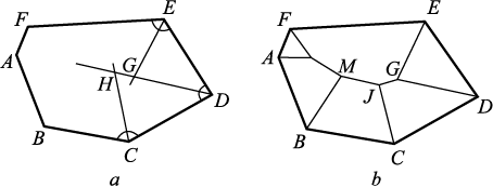
In mechanical engineering, a significant portion of parts, driven by design processability requirements, comprise rotational surfaces and polyhedrons. Consequently, die forging in practice often involves parts derived from flat billets featuring planar elements [23 – 25]. This study focuses on the simplest scenario, addressing the challenge of constructing an equidistant curve for a contour represented by a piecewise linear closed line, namely, a polygon (Fig. 1, а).
Fig. 1. Equidistant construction scheme |
The equidistant line of two intersecting straight lines corresponds to the bisector of the angle formed by their intersection. Our approach initiates from the smallest angle of the polygon. Thus, the first equidistant line of the contour constitutes the bisector of the angle at vertex D. Subsequently, we extend this line by drawing bisectors of the two adjacent angles, intersecting at points G and H, which mark the termination points of the first equidistant lines at the closest intersection point G with the bisectors of the neighboring angles.
Next, we disregard the DE contour side. The equidistant lines were formed by the bisectors of the adjacent angles to the DE contour side. We proceed until reaching the intersection of contour sides FE and CD, adjacent to the discarded line.
The dimensionality of the contour has decreased by one: instead of a hexagon, we will now consider a pentagon. Obviously, now the smallest angle in the contour polygon will be the newly obtained angle. The procedure is repeated, but the new equidistant line is drawn not from the contour angle, but from the end point of the last equidistant line – point G. Then we again search for the smallest contour angle among the remaining ones (this is the angle at vertex F) and repeat the above algorithm until the polygon is reduced actually to a triangle. As we know from geometry, in a triangle the bisectors always intersect in one point, so to complete building the equidistant lines it is sufficient to connect the points where the consecutive actions were stopped. Building is over (the result is shown in Fig. 1, b).
This approach can be applied to construct the equidistant line of any polygon. Currently, the algorithm has been implemented in the DELPHI visual programming environment. Additionally, a similar algorithm has been devised for a piecewise-nonlinear multilink contour [26 – 28].
Computer modeling
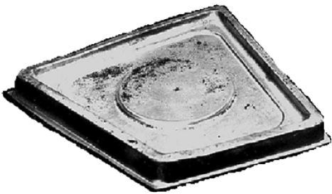
Let us explore the capabilities of the developed method and software system through an example of modeling the forming of a stamped forging with contour ribbing (Fig. 2).
Fig. 2. Stamped forging with technological cutout |
To swiftly assess the viability of incorporating a boss (or a cutout) in the given forging, the developed software system [29 – 31] was employed to simulate the metal flow pattern by adjusting the position of the circle center and the radius value. Analysis of the results demonstrates that directing the metal flow towards the boss (or cutout) mitigates the unevenness of metal distribution into the die cavity, thereby confirming its practical applicability.
To conduct the forging forming simulation, we utilized software built upon the developed method.
When conducting the modeling, certain requirements must be considered. Only geometric elements that do not impact the design of the final product can be altered. These include parameters such as the width and height of the gutter threshold, the radius of the boss, the initial thickness of the billet, or the upset increment. Notably, the radius of the boss is included in these variables because it will be replaced by a 240 mm diameter hole in the finished part, and the boss will be removed during machining. Throughout the calculation process, the size of the boss functions as a control factor, allowing for the generation of various metal flow patterns along the die impression surface and, consequently, different profiles of the stiffener.
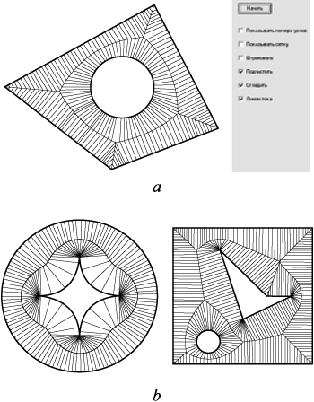
Fig. 3, a schematically illustrates the pattern of metal flow along the forging web.
Similarly, it is feasible to derive the metal flow pattern for contours of any complexity, as depicted in Fig. 3, b.
Fig. 3. Model of the metal flow pattern |
Physical modeling
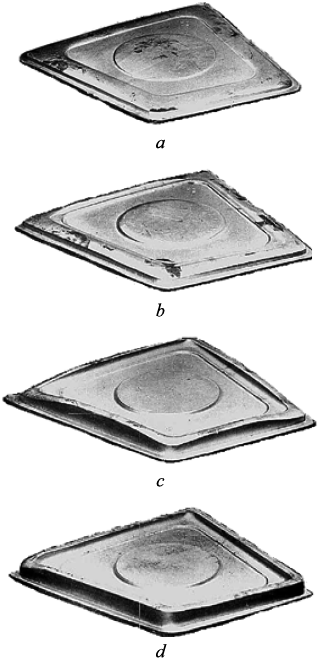
To validate the results of the analysis regarding the forming of the stamped forging with contour ribbing, an experiment was conducted under industrial conditions involving the stage-by-stage upsetting of flat forged billets (Fig. 4). These billets were composed of AK6 alloy and processed on a hydraulic press with a strain force of 150 MN.
Fig. 4. Forming of stamped forgings |
The forging could not be fully formed due to the insufficient capacity of the hydraulic press. At the latest studied stage of upsetting, the boss was already formed in full, while one of the corner areas did not reach the designed height (Fig. 4, d).
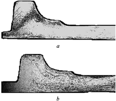
The central areas of the stiffeners significantly outpaced the corner areas in terms of forming. Consequently, metal flowed over the die cavities beneath the stiffeners in the central areas, resulting in poor macrostructure of the product. This deficiency manifested in an inadequate alignment of metal fibers featuring sharp bends (Fig. 5, a), which could potentially lead to undercutting of the stiffener from the flash gutter side.
Fig. 5. Macrostructure of the forging |
These observations were corroborated by the utilization of software for modeling various technological alternatives aimed at producing the specified serial forging. As previously noted, the forging could not be stamped in a single pass using the manufacturer’s proposed technology.
The analysis of the calculation results has led to recommendations regarding the design of the die and the manufacturing process for producing a series of forgings. Despite the introduction of a large-radius boss, which failed to eliminate the uneven formation of individual stiffeners, thereby risking defects, it is proposed to conduct stamping in two passes using a single final die. This involves cutting a hole in the center of the forging after the first pass.
Stamping conducted in industrial conditions, while incorporating these recommendations, has validated their effectiveness. A hydraulic press with a capacity of up to 100 MN proved sufficient for achieving a high-quality product. Notably, the macrostructure of the stamped forging saw significant improvement, resulting in smooth alignment of metal fibers at the base of the stiffeners (Fig. 5, b). This effectively prevents the occurrence of defects such as “shooting-through”.
Conclusions
The software system can serve a diverse functional purpose: facilitating rapid analysis of the metal flow pattern and computation of billet forming across its strain stages. This capability enables users to select various geometrical parameters of the die impression, thereby obtaining different metal flow patterns and stiffener profiles. By prioritizing configurations that ensure the most uniform filling of die cavities with metal beneath the stiffeners, manufacturers can guarantee defect-free production of their products. The outcomes of the presented development can be effectively leveraged to further advance modeling efforts concerning the plastic flow of metal in the metalworking process [32 – 35].
References
1. Sosenushkin E.N., Kadymov V.A., Yanovskaya E.A. Mathematical modeling of metal flow along planes with free flow into ribs. In: Machine Tool Construction and Innovative Mechanical Engineering. Problems and Growth Points: Proceedings of the All-Russ. Sci.-Tech. Conf. in the Ufa State Avia. Tech. University. Ufa: RIK USATU; 2019:337–342. (In Russ.).
2. Ushakov I.V., Safronov I.S. Directed changing properties of amorphous and nanostructured metal alloys with help of nanosecond laser impulses. CIS Iron and Steel Review. 2021;22:77–81. https://doi.org/10.17580/cisisr.2021.02.14
3. Kondratenko V.E., Devyatiarova V.V., Albul S.V., Kartyshev D.S. Improving methodology for calculating scaffolding formwork of monolithic slabs in building constructions. IOP Conference Series: Materials Science and Engineering. 2020;971(5):052037. https://doi.org/10.1088/1757-899x/971/5/052037
4. Bardovsky A.D., Gerasimova A.A., Basyrov I.I. Constructive solutions for upgrading of the drive of processing equipment. IOP Conference Series: Materials Science and Engineering. 2020;709(2):022015. https://doi.org/10.1088/1757-899x/709/2/022015
5. Shinkaryov A.S., Ozherelkov D.Yu., Pelevin I.A., Eremin S.A., Anikin V.N., Burmistrov M.A., Chernyshikhin S.V., Gromov A.A., Nalivaiko A.Yu. Laser fusion of aluminum powder coated with diamond particles via selective laser melting: Powder preparation and synthesis description. Coatings. 2021;11(10):1219. https://doi.org/10.3390/coatings11101219
6. Kulagin Yu.A., Baranov E.O., Shinkarev A.S., Avatinyan G.A., etc. New aspects of the development of ice and laser technologies for sports of higher achievements. Kholodil’naya tekhnika. 2016;(12):36–43. (In Russ.).
7. Ganzulenko O.Y., Petkova A.P. Simulation and approbation of the marking laser process on metal materials. Journal of Physics: Conference Series. 2021;1753(1):012016. https://doi.org/10.1088/1742-6596/1753/1/012016
8. Brunman V.E., Vataev A.S., Volkov A.N., Petkova A.P., Plotnikov D.G. Optimizing pump-drive operation to improve the energy-efficiency of oil extraction. Russian Engineering Research. 2017;37(6):479–484. https://doi.org/10.3103/S1068798X17060089
9. Kadymov V.A., Sosenushkin E.N., Yanovskaya E.A. Contact problems of plastic flow in a thin layer: Theory, analysis of solutions, and applications. Journal of Machinery Manufacture and Reliability. 2022;51(3):206–215. https://doi.org/10.3103/S1052618822030062
10. Kushnarev A.V., Kirichkov A.A., Shestak V.D., Timofeev V.V., Bogatov A.A. Introduction of wheel production on a new pressing and rolling line. Steel in Translation. 2010;40(12):1098–1100. https://doi.org/10.3103/S0967091210120181
11. Pogrebnyak R.P. Experimental study of shape of a railway wheel rolled billet. Proizvodstvo prokata. 2012;(2):29–33. (In Russ.).
12. Snitko S.A., Yakovchenko A.V. Influence of the axial reduction conditions on the variation in the thickness of a wheel rim at the initial stage of rolling. Metallurgist. 2017;61(5-6):387–393. https://doi.org/10.1007/s11015-017-0505-x
13. Kleiner M., Geiger M., Klaus A. Manufacturing of lightweight components by metal forming. CIRP Annals. 2003;52(2):521–542. https://doi.org/10.1016/S0007-8506(07)60202-9
14. Park C.S., Ku T.W., Kang B.S., Hwang S.M. Process design and blank modification in the multistage rectangular deep drawing of an extreme aspect ratio. Journal of Materials Processing Technology. 2004;153–154:778–784. https://doi.org/10.1016/j.jmatprotec.2004.04.306
15. Pichuev A.V., Petrov V.L. Equivalent circuit for mine power distribution systems for the analysis of insulation leakage current. Mining Science and Technology (Russia). 2023;8(1):78–86. (In Russ.). https://doi.org/10.17073/2500-0632-2023-01-72
16. Sukhorukova M.A., Ivannikov A.L. Vehicle accident risk assessment in mines. Mining Informational and Analytical Bulletin. 2020;(6–1):224–232. https://doi.org/10.25018/0236-1493-2020-61-0-224-232 (In Russ.).
17. Tatarnikov N.N., Yusupov V.S., Belelyubsky B.F. Manufacturing of work-rolls with higher geometry and roughness requirements for rolling the thinnest strip. AIP Conference Proceedings. 2023;2697:030012. https://doi.org/10.1063/5.0135274
18. Kim S.H., Chung S.W., Padmanaban S. Investigation of lubrication effect on the backward extrusion of thin-walled rectangular aluminum case with large aspect ratio. Journal of Materials Processing Technology. 2006;180(1–3):185–192. https://doi.org/10.1016/j.jmatprotec.2006.06.003
19. Il’yushin A.A. Plasticity. Moscow: Gostekhizdat; 1948:376. (In Russ.).
20. Solomonov K.N., Kostarev I.V., Abashkin V.P. Modeling of Processes of Volumetric Stamping and Forging of Flat Billets. Moscow: MISIS; 2008:128. (In Russ.).
21. Лисунец Н.Л., Соломонов К.Н., Цепин М.А. Объемная штамповка алюминиевых заготовок. Москва: Машиностроение; 2009:172.
22. Lisunets N.L., Solomonov K.N., Tsepin M.A. Volumetric Stamping of Aluminum Billets. Moscow: Mashinostroenie; 2009:172. (In Russ.).
23. Chichenev N.A., Chicheneva O.N., Karfidov A.O., Pashkov A.N. Selection of laser processing parameters for hot stamping tools based on mathematical planning of the experiment. CIS Iron and Steel Review. 2021;22:37–40. https://doi.org/10.17580/cisisr.2021.02.07
24. Kiani-Rashid A.R., Rounaghi S.A. The new methods of graphite nodules detection in ductile cast iron. Materials and Manufacturing Processes. 2011;26(2):242–248. https://doi.org/10.1080/10426914.2010.520788
25. Di Cocco V., Iacoviello F., Cavallini M. Damaging micromechanisms characterization of a ferritic ductile cast iron. Engineering Fracture Mechanics. 2010;77(11):2016–2023. https://doi.org/10.1016/j.engfracmech.2010.03.037
26. Milenin A., Petrov P., Petrov M., Krutina E. Numerical model of fracture in magnesium alloys during forming processes. Steel Research International. 2012;SPL:847–850.
27. Chaus A.S., Soyka J., Pokrovsky A.I. The effect of hot plastic deformation on changes in the microstructure of cast iron with spherical graphite. The Physics of Metals and Metallography. 2013;114(1):4–104. https://doi.org/10.1134/S0031918X13010031
28. Соломонов К.Н., Федоринин Н.И., Тищук Л.И. Методика построения линии раздела течения металла в процессах осадки плоских заготовок. Вестник научно-технического развития. 2016;(2):36–55.
29. Solomonov K.N., Fedorinin N.I., Tishchuk L.I. Method of constructing a metal flow dividing line during flat billet precipitation. Vestnik nauchno-tekhnicheskogo razvitiya. 2016;(2):36–55. (In Russ.).
30. Zhang Y.Q., Jiang S.Y., Zhao Y.N., Shan D.B. Isothermal precision forging of complex-shape rotating disk of aluminum alloy based on processing map and digitized technology. Materials Science and Engineering: A. 2013;580:294–304. https://doi.org/10.1016/j.msea.2013.05.059
31. Zheng J.H., Lin J.G., Lee J., Pan R., Li C., Davies C.M. A novel constitutive model for multi-step stress relaxation ageing of a pre-strained 7xxx series alloy. International Journal of Plasticity. 2018;106:31–47. https://doi.org/10.1016/j.ijplas.2018.02.008
32. Максимов Е.А., Шаталов Р.Л., Крутина Е.В. Методика расчета деформационных и энергосиловых параметров при совмещенной ротационной вытяжке и поперечной прокатке дисков колес. Черные металлы. 2019;(1):34–38.
33. Maksimov E.A., Shatalov R.L., Krutina E.V. Calculation technique for deformation and energy-power parameters in combined rotary drawing and cross rolling of wheel disks. Chernye metally. 2019;(1):34–38. (In Russ.).
34. Chichenev N.A., Gorbatyuk S.M., Naumova M.G., Morozova I.G. Using the similarity theory for description of laser hardening processes. CIS Iron and Steel Review. 2020;19:44–47. https://doi.org/10.17580/cisisr.2020.01.09
35. Yong P., Shuncheng W., Kaihong Z., Wenjun Q., Hexing C., Haitao Z., Influence of the pressing time during the liquid stamping of the deformable aluminum alloy 6061 on its mechanical. Special Casting & Nonferrous Alloys. 2013;33(12):1152–1157.
36. Gorbatyuk S., Pashkov A., Chichenev N. Improved copper-molybdenum composite material production technology. Materials Today: Proceedings. 2019;11(1):31–35. https://doi.org/10.1016/j.matpr.2018.12.102
37. Solomonov K. Development of software for simulation of forming forgings. Procedia Engineering. 2014;81:437–443. https://doi.org/10.1016/j.proeng.2014.10.019
38. Singh A., Agrawal A. Investigation of surface residual stress distribution in deformation machining process for aluminum alloy. Journal of Materials Processing Technology. 2015;225:195–202. https://doi.org/10.1016/j.jmatprotec.2015.05.025
39.
About the Authors
K. N. SolomonovRussian Federation
Konstantin N. Solomonov, Dr. Sci. (Eng.), Prof. of the Chair of Social, Humanitarian, Natural Sciences and General Professional Disciplines
75a Uritskogo Str., Voronezh 394026, Russian Federation
L. I. Tishchuk
Russian Federation
Lyudmila I. Tishchuk, Assist. Prof. of the Chair of Social, Humanitarian, Natural Sciences and General Professional Disciplines
75a Uritskogo Str., Voronezh 394026, Russian Federation
S. M. Gorbatyuk
Russian Federation
Sergei M. Gorbatyuk,Dr. Sci. (Eng.), Prof. of the Chair “Engineering of Technological Equipment”
4 Leninskii Ave., Moscow 119049, Russian Federation
S. A. Snitko
Russian Federation
Sergei A. Snitko, Dr. Sci. (Eng.), Assist. Prof., Head of the Chair “Metal Forming”
58 Artema Str., Donetsk, Donetsk People’s Republic 283001, Russian Federation
O. N. Chicheneva
Russian Federation
Ol’ga N. Chicheneva, Cand. Sci. (Eng.), Assist. Prof.
4 Leninskii Ave., Moscow 119049, Russian Federation
Review
For citations:
Solomonov K.N., Tishchuk L.I., Gorbatyuk S.M., Snitko S.A., Chicheneva O.N. Modeling the pattern of metal flow during forming of forgings from a flat billet. Izvestiya. Ferrous Metallurgy. 2023;66(6):768-774. https://doi.org/10.17073/0368-0797-2023-6-768-774
JATS XML


