Scroll to:
Simulation of a new process of mixing liquid metal in CCM mold with rotating cooling jacket with vertical ribs
https://doi.org/10.17073/0368-0797-2023-6-733-742
Abstract
The article proposes a new technology of filling the CCM mold with liquid metal and mixing it. The original patented device consists of a closed bottom nozzle and a rotating jacket. Experimental studies of liquid metal flow in a mold are long, complex and time-consuming, therefore, in the work was used mathematical modeling by numerical method. The objects of research are the hydrodynamic and thermal flows of liquid metal during the new process of steel casting into a CCM mold of rectangular cross-section, and the result is a spatial mathematical model that describes the flows and temperatures of liquid metal in the mold. To simulate the processes occurring during the metal flow in the mold, the authors used a specially created software package. The theoretical calculations are based on the fundamental equations of hydrodynamics, the equations of mathematical physics (equation of thermal conductivity taking into account mass transfer) and a proven numerical method. The area under study is divided into elements of finite dimensions, for each element a formulated system of equations is written in a difference form. The result is the velocity and temperature fields of the metal flow in the mold volume. According to the developed numerical schemes and algorithms, a calculation program was compiled. The paper considers an example of calculating the steel casting into a mold of rectangular cross-section and flow diagrams of liquid metal over various mold sections. Vector flows of liquid metal in various mold sections are clearly presented for different rotary speed of the rotating jacket. The authors identified the areas of intense turbulence and presented the results of the problem numerical solution in graphical form by diagrams of the velocity fields of liquid metal flows and their temperature over various mold sections.
Keywords
For citations:
Odinokov V.I., Evstigneev A.I., Dmitriev E.A., Karpenko V.A. Simulation of a new process of mixing liquid metal in CCM mold with rotating cooling jacket with vertical ribs. Izvestiya. Ferrous Metallurgy. 2023;66(6):733-742. https://doi.org/10.17073/0368-0797-2023-6-733-742
Introduction
There is an increasing interest in refining the techniques for managing the flow and blending of liquid metal in Continuous Casting Molds (CCM), including the tools needed for these processes.
Experimental analysis of liquid metal movement within molds is notably complex and demands significant time, prompting a shift towards mathematical modeling, particularly through numerical methods, for these studies.
The strategies for enhancing the distribution and integration of liquid metal in CCM are well-documented in numerous national and international studies, highlighting the impact on ingot quality.
The traditional method [1 – 5] for ensuring that liquid metal washes the mold walls more evenly to achieve a uniform structure around the ingot’s perimeter involves the following approach: the metal from the tundish is introduced into the mold through the holes of a closed-bottom submerged nozzle. These holes are positioned at angles of 180° relative to each other.
Innovative techniques for directing liquid metal from the nozzle into the mold have been developed. These methods vary the angle and positioning of nozzle openings [6], employ eccentrically located holes [7], use multiple nozzles [8], apply electromagnetic stirring within the mold [9], and introduce metal through deflectors [10].
Additional studies [11 – 13] introduce novel approaches and practical findings on optimizing the introduction and amalgamation of liquid metal into the CCM [11 – 13].
Researchers are actively developing models for the mathematical analysis of liquid metal flow and steel solidification in molds, using techniques such as digital modeling [14], examining the role of secondary flow in rotary electromagnetic stirring during continuous casting [15], studying metal flow inside the CCM [16; 17], investigating turbulent flow and particle transport [18], and creating models for metal solidification [19 – 21] and heat transfer during solidification [22 – 24].
They have also developed mathematical models for various liquid metal supply methods into the mold, allowing for the evaluation of specific devices’ efficiency [7; 8].
Yet, there’s a notable gap in the mathematical modeling of these processes, especially using numerical methods, limiting the innovation of new technologies for liquid metal supply and mixing in CCMs.
Despite past achievements, the design and modeling of melt supply and mixing processes and devices are not thoroughly explored, highlighting the importance of such research.
Therefore, it’s crucial to develop new melt supply and mixing processes and their mathematical models. This will enable the prediction of new devices’ performance and efficiency early in the design stage.
This paper introduces innovative technologies for casting liquid metal into the mold, utilizing rotational effects for improved mixing.
The goal is to establish a mathematical model that captures the hydrodynamic processes in the CCM mold with this new steel supply method. It aims to demonstrate the advantages of controlled rotation for liquid metal supply and mixing over the conventional free rotation of the submerged nozzle during steel casting.
We describe and analyze a novel process for liquid metal supply and mixing in the CCM mold [25], which, unlike previous methods [26; 27], offers extensive control over mixing speed. This control is crucial for achieving higher quality continuous ingots.
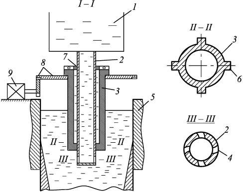
Fig. 1 illustrates the design of a specific device. Metal is transferred from the tundish (1) into the mold (5) via a closed-bottom submerged nozzle (2), which is equipped with off-center holes (4). A refractory jacket (3) featuring ribs (6) is fitted around the submerged nozzle’s outer surface, just above its discharge holes, with a small gap in between. This jacket is linked to a rotating mechanism, comprised of an axial bearing (7), a gearbox (8), and an electric motor (9).
Fig. 1. Scheme of a device for supply and mixing of steel |
The process in question is dynamic, yet it’s modeled as if it were steady under certain simplifying assumptions. The submerged nozzle and the rotating refractory jacket share the same square shape at their outlets. Thus, as the jacket rotates, its edges stir the liquid metal within the mold.
The rotation direction causes one side of the refractory jacket’s square edge to push the metal outward, while the opposite side draws it in. In this model, the submerged nozzle is considered to be fixed, with metal movement in and out of the jacket’s edges depending on the rotation speed and the square dimensions of the jacket. This idealized scenario is thoroughly explained in [1], allowing the process to be viewed as steady for the purpose of this analysis. It’s important to note that the formation of a solid metal crust on the mold edges is not accounted for in this model.
The medium, which is liquid metal, is considered incompressible. Let’s consider the equations of hydrodynamics. The following equations are valid for the flow of a Newtonian, viscous, incompressible fluid when the process is stationary:
| \[{\sigma _{ij,j}} + F_i^* = I_i^*;{\rm{ }}I_i^* = \rho \left( {{{\dot v}_i} + {v_k}\frac{{\partial {v_i}}}{{\partial {x_k}}}} \right);\] | (1) |
| \[{\sigma _{ij}} - \sigma {\delta _{ij}} = 2\mu {\xi _{ij}};{\rm{ }}{\xi _{ij}} = \frac{1}{2}\left( {{v_{i,j}} + {v_{j,i}}} \right);\] | (2) |
| vi, i = 0; i = 1, 2, 3; | (3) |
| \[\frac{{d\theta }}{{d\tau }} = a\Delta \theta ;{\rm{ }}\frac{{d\theta }}{{d\tau }} = {v_i}\frac{{\partial \theta }}{{\partial {x_i}}};{\rm{ }}i = 1,{\rm{ }}2,{\rm{ }}3,\] | (4) |
here σij are the components of the stress tensor; ξij are the components of the strain rate tensor; δij is Kronecker’s delts; p is the pressure at a given point (p = –σ); σ is the hydrostatic stress; μ is the viscosity coefficient, (g·s)/cm2; vi is the velocity projections along the coordinate axes xi (i = 1, 2, 3); ρ is the density of the liquid metal; \(F_i^*\) is the projection of the specific volume force on the coordinate axis xi (i = 1, 2, 3); τ is time; Δ is the Laplace operator; θ is the temperature; a = λ/(cγ) is the temperature-conductivity ratio; λ is the heat transfer coefficient; c is the specific heat capacity; γ is the density, all of which are considered constants in this context.
For the stationary process:
\[{\dot v_i} = \frac{{\partial {v_i}}}{{\partial \tau }} = 0.\]
The thermal conductivity equation considers mass transfer and the condition of stationarity.
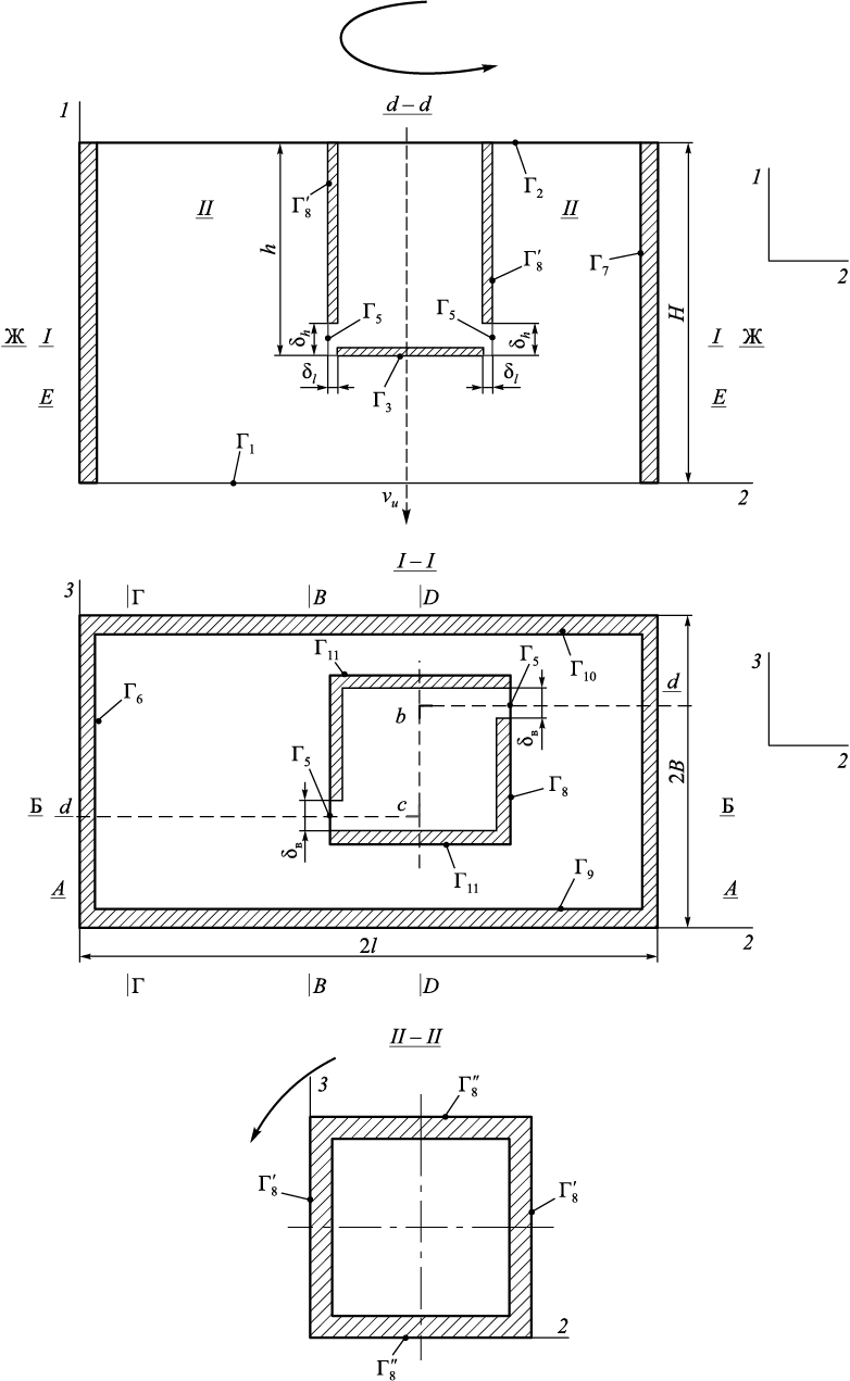
Fig. 2 illustrates the computational scheme for the process being examined.
Fig. 2. Formalized design scheme of metal casting into the mold |
The boundary conditions of the problem are defined as follows (Fig. 2):
| \[\begin{array}{c}{\left. {{\sigma _{11}}} \right|_{{\Gamma _2}}} = {p_1};{\left. {{\rm{ (}}{\sigma _{12}} = {\sigma _{13}})} \right|_{{\Gamma _i}}} = 0;{\rm{ }}i = 1 \div 3;\\{\left. {{\rm{(}}{\sigma _{21}} = {\sigma _{23}})} \right|_{{\Gamma _i}}} = 0;{\rm{ }}i = 5 \div 8;\\{\left. {{\rm{(}}{\sigma _{31}} = {\sigma _{32}})} \right|_{{\Gamma _i}}} = 0;{\rm{ }}i = 9 \div 11;\\{\left. {{\rm{(}}{\sigma _{21}} = {\sigma _{23}})} \right|_{{{\Gamma '}_{\rm{8}}}}} = 0;{\rm{ }}{\left. {{\rm{(}}{\sigma _{31}} = {\sigma _{32}})} \right|_{{{\Gamma '''}_{\rm{8}}}}} = 0;\\{\left. {{v_2}} \right|_{{\Gamma _5}}} = {v^*};\\{\left. {{v_3}} \right|_{{{\Gamma ''}_{\rm{8}}}}} = {V_t};\\{\left. {{v_2}} \right|_{{{\Gamma '}_{\rm{8}}}}} = {V_t};\\{\left. {{v_1}} \right|_{{\Gamma _{\rm{1}}}}} = {v_u};\\{\left. {{v_1}} \right|_{{\Gamma _{\rm{3}}}}} = 0;\\{\left. {{v_2}} \right|_{{\Gamma _i}}} = 0;{\rm{ }}i = 6 \div 8;\\{\left. {{v_3}} \right|_{{\Gamma _i}}} = 0;{\rm{ }}i = 9 \div 11.\end{array}\] | (5) |
The boundary conditions were applied to solve the thermal conductivity equation (4):
| \[\begin{array}{c}{\left. \theta \right|_{{\Gamma _i}}} = \theta _i^*;{\rm{ }}i = 1 \div 10;\\{\left. q \right|_{{\Gamma _i}}} = q_i^*;{\rm{ }}i = 6,{\rm{ }}7,{\rm{ }}9,{\rm{ }}10.\end{array}\] | (6) |
here vu is the speed at which the ingot is pulled (Fig. 2); \(v_2^*\) is the speed of liquid metal exiting through the holes of the submerged nozzle; the given functions of metal temperature distribution on surfaces Гi are denoted as \(\theta _i^*\); while \(q_i^*\) refers to the heat flows through surfaces Гi ; obtained from experimental data; the preset temperature of the metal exiting through the hole Г5 is specified as \(\theta _5^*\).
The numerical scheme and algorithm for solving the system of equations (1) ‒ (4) under the boundary conditions (5), (6) are described in detail in [28], utilizing a numerical method that has been extensively tested.
Below, we present the results of the numerical solution for the problem across different sections of the mold, along with an analysis of these results.
Results of numerical calculation
We set the mold dimensions as follows: Н = 100 cm; В = 12.5 cm; l = 100 cm; h = 20 cm; b = 7.5 cm; δh = 8.5 cm; δB = 1.5 cm; δ1 = 1.5 cm; vu = 1 m/min = 1.66 cm/s. For the stationary process, the value v\(^{*}\) was determined from the equality of the second volumes:
\[{v_u}Bl = {v^*}{\delta _n}{\delta _B} \Rightarrow {v^*} = \frac{{{v_u}Bl}}{{{\delta _n}{\delta _B}}}.\]
The temperature of the liquid steel flowing out of the hole (Г5 ) was set to \({\left. {{\theta ^*}} \right|_{{\Gamma _5}}}\) = 1600 °С. The temperature on the surfaces of the submerged nozzle (Fig. 2) Гi (i = 3, 8, 8′, 11) was determined from experimental data to be \({\left. {{\theta ^*}} \right|_{{\Gamma _i}}}\) = 1550 °С, i = 3, 8, 8′, 11. On the surface Г2 (Fig. 2) there is a liquid slag “jacket” with a temperature of \({\left. {{\theta ^*}} \right|_{{\Gamma _2}}}\) = 1550 °С.
Constants are defined as follows λ = 0.29 W/(cm·s); c = 444.47 J/(kg·s); γ = 7.8 g/cm3. The viscosity factor μ = 2.1·10\(^–\)4 (kg·s)/m2 used in equations (2) was adopted based on [29].
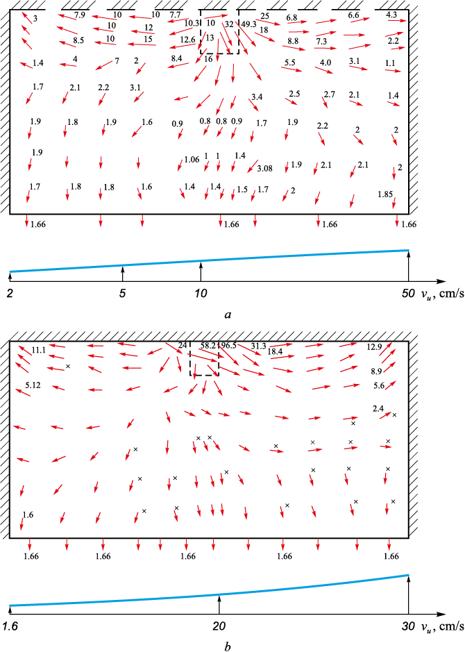
Fig. 3 illustrates the metal flows in the cross-section А ‒ А as the jacket rotates at speed (n) of 30 and 50 rpm. The low patterns are comparable, yet the intensity of the flows increases at n = 50 rpm (Fig. 3, b). In cross-section А ‒ А, metal flow near the submerged nozzle appears chaotic. Areas where the metal temperature exceeds the crystallization point are indicated by asterisks in Fig. 3, b, highlighting regions of higher thermal variance. This suggests a more uneven distribution of temperature within the metal flows across this cross-section.
Fig. 3. Velocity field of metal flows in the mold cross-section A ‒ A at n = 30 (a) and 50 rpm (b) |
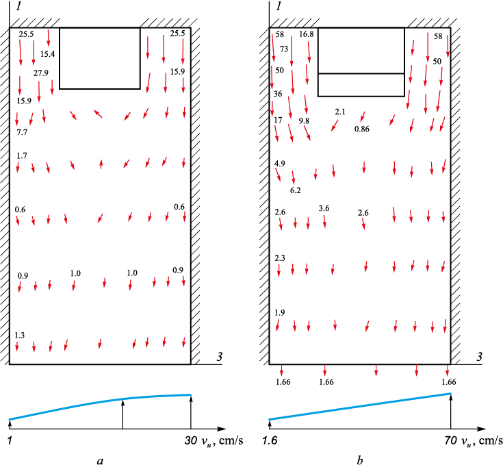
In Fig. 4 the metal flows in the vertical cross-section В ‒ В, which captures the area where metal exits the submerged nozzle, are depicted. This figure compares the flow dynamics at rotational speeds of 30 and 50 rpm, with all flow vectors predominantly pointing downwards. Consistent with expectations, flow intensity is higher at the increased rotational speed of 50 rpm.
Fig. 4. Velocity field of metal flows in the mold cross-section B ‒ B at n = 30 (a) and 50 rpm (b) |
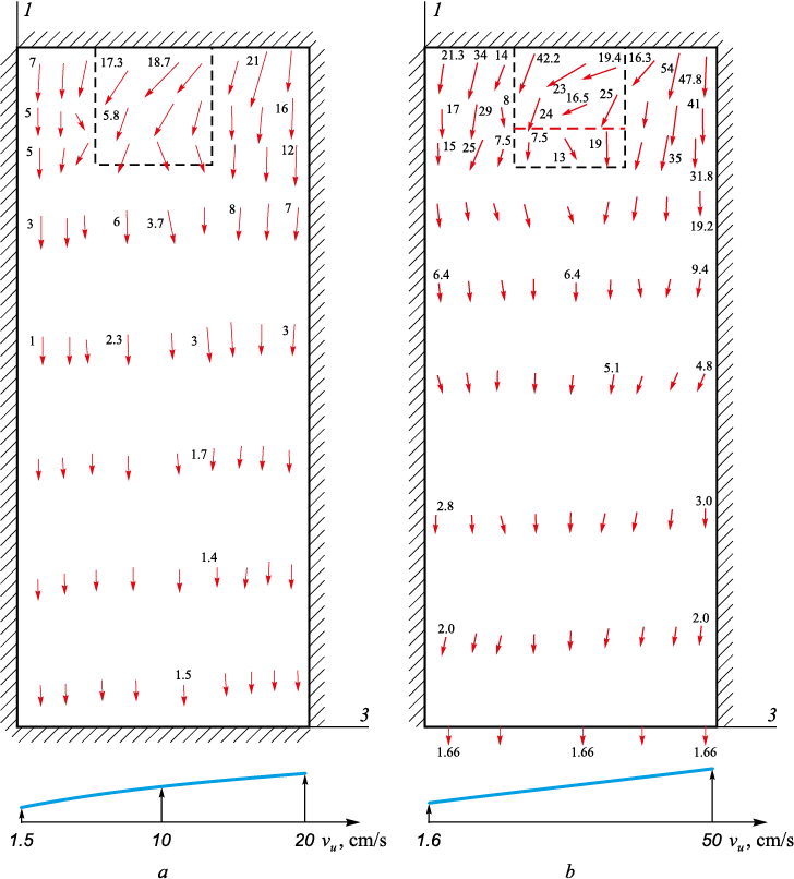
Fig. 5, a, presents the metal flows in cross-section D ‒ D (Fig. 2) when the jacket rotates at 30 rpm and at 50 rpm. At n = 30 rpm (Fig. 5, a), small vortices are observed beneath the submerged nozzle, specifically at its center. However, at the higher speed of 50 rpm, these vortices disappear. The metal flow rate near the side edges of the mold is significantly higher than that under the submerged nozzle.
Fig. 5. Velocity field of metal flows in the mold cross-section D ‒ D at n = 30 (a) and 50 rpm (b) |
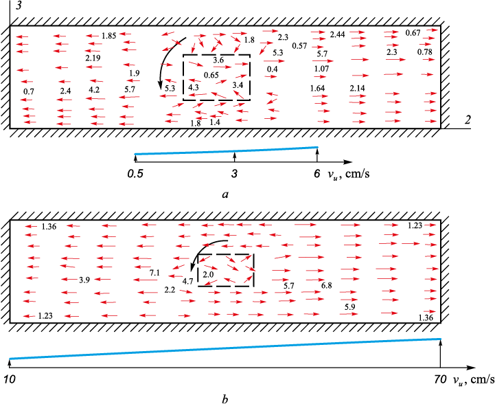
In Fig. 6, the metal flows are illustrated in the horizontal cross-section Е ‒ Е, with the jacket rotating at speeds of 30 and 50 rpm.
Fig. 6. Velocity field of metal flows in the mold cross-section Е ‒ Е at n = 30 (a) and 50 rpm (b) |
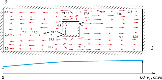
The flow vectors show little difference in terms of motion patterns and velocities. At a rotational speed of 50 rpm, Fig. 7 illustrates the metal flows in the horizontal section of the submerged nozzle as it moves through the outlets (cross-section Ж ‒ Ж). The pattern of metal flow is similar to that observed in cross-section Е ‒ Е (Fig. 6), albeit more intense.
Fig. 7. Velocity field of metal flows in the mold cross-section Ж ‒ Ж at n = 50 rpm |
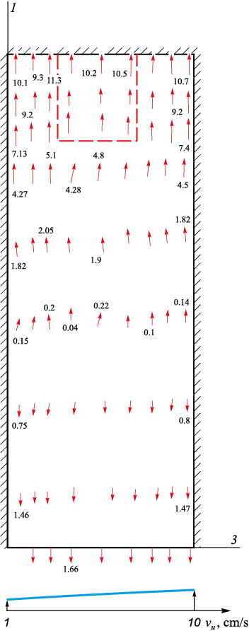
When the rotation speed reaches 50 rpm, the metal can penetrate into the slag cushion along the narrow mold walls. Fig. 8 displays the motion field of the liquid metal (cross-section Г′ ‒ Г′). In this case, the liquid metal moves upward, covering half of the vertical plane of the mold’s side wall, and accelerates at the slag jacket, reaching a speed of 10 cm/s. In the cross-section D ‒ D, metal moves swiftly downward from the slag jacket (Fig. 5, b). This rapid movement suggests the potential formation of vortices beneath the slag jacket. Such vorticity in the metal flow is not necessarily benign. It raises the concern that slag could become entrapped within the continuous ingot, negatively impacting the quality of the ingot.
Fig. 8. Velocity field of metal flows in the mold cross-sectionn Г′ ‒ Г′ at n = 50 rpm |
Conclusions
The theoretical study produced numerical results:
‒ in cases of forced mixing of liquid metal within a rectangular cross-section mold, the mold walls are intensively washed, significantly aiding in the transfer of heat from the liquid metal to the mold walls;
‒ within the mold, particularly in its upper section, there is observed accelerated movement of liquid metal flows;
‒ on narrow mold walls, liquid metal is propelled (even at 30 rpm) towards the slag jacket area, potentially allowing some of the slag to mix into the continuously cast ingot. To prevent this issue, the submerged nozzle equipped with the rotating jacket can be positioned deeper into the mold. This adjustment requires an increase in mold height.
References
1. Dyudkin D.A., Kisilenko V.V., Smirnov A.N. Production of Steel. Vol. 4. Continuous Casting of Metal. Moscow: Teplotekhnik; 2009:528. (In Russ.).
2. Efimov V.A. Casting and Crystallization of Steel. Moscow: Metallurgiya; 1976:552. (In Russ.).
3. Akimenko A.D., Girskii V.E., Gus’kov A.I. Influence of methods of metal supply to a mold on formation of axial zone in a square ingot. Stal’. 1973;(5):408–409. (In Russ.).
4. Odinokov V.I., Dmitriev E.A., Evstigneev A.I. Numerical modeling of the process of filling the CCM mold with metal. Izvestiya. Ferrous Metallurgy. 2017;60(6):493–498. (In Russ.). https://doi.org/10.17073/0368-0797-2017-6-493-499
5. Proceedings of the Int. Symp. on Electromagnetic Processing of Materials. October 25–28, 1994. Nagoya, Japan: ISIJ; 1994:580.
6. Stulov V.V., Matysik V.A., Novikov T.V., Shcherbakov S.V., Chistyakov I.V., Plotnikov A.P. Development of a New Method for Casting Slab Blanks in CCM. Vladivostok: Dal’nauka; 2008:156. (In Russ.).
7. Odinokov V.I., Dmitriev E.A., Evstigneev A.I. Mathematical modeling of metal flow in crystallizer at its supply from submersible nozzle with eccentric holes. Izvestiya. Ferrous Metallurgy. 2018;61(8):606–612. (In Russ.). https://doi.org/10.17073/0368-0797-2018-8-606-612
8. Kuberskii S.V., Semiryagin S.O., Fedorov O.V. Calculations of Technological and Design Parameters of CCM: Tutorial. Alchevsk: DONSTU; 2006:146. (In Russ.).
9. Smirnov A.A., Niskovskikh V.M., Kulikov V.I. Investigation of electromagnetic mixing of metal in slab CCM by modeling method. In: Improving the Structures, Research and Calculation of CCM: Coll. of Sci. Papers. Moscow: VNIIMETMASh; 1987:85–90. (In Russ.).
10. Odinokov V.I., Evstigneev A.I., Dmitriev E.A. Numerical modelling of metal filling in CCM mold completed with deflector. Izvestiya. Ferrous metallurgy. 2019;62(10):747–755. (In Russ.). https://doi.org/10.17073/0368-0797-2019-10-747-755
11. Nartst Kh.-P., Kellerer S., Shtakhelberger K., Merval’d K., Fedeshpil’ K., Val’ G. Innovative solutions and practical results of continuous slab casting technology. Chernye metally. 2003;(11):34–38. (In Russ.).
12. Vimmer F., Tene X., Pekshtainer L. High-speed casting of small-grade billets on CCM with Diamond mold. Stal’. 1999;(6):22–26. (In Russ.).
13. Aikhinger A., Frauenkhuber K., Khedl’ X., Merval’d K. Modern equipment for high-performance continuous casting. Stal’. 2000;(3):25–28. (In Russ.).
14. Oler K., Odental’ Kh.-Yu., Pfaifer G., Lemanovich I. Digital modeling of metal flow and solidification in CCM for casting thin slabs. Chernye metally. 2002;(8):22–30. (In Russ.).
15. Davidson P.A., Boysan F. The importance of secondary flow in the rotary electromagnetic stirring of steel during continuous casting. Applied Scientific Research. 1987;44(1–2):241–259. http://doi.org/10.1007/BF00412016
16. Thomas B.G., Mika L.J., Najjar F.M. Simulation of fluid flow inside a continuous slab casting machine. Metallurgical Transactions B. 1990;21(2):387–400. http://doi.org/10.1007/BF02664206
17. Thomas B.G., Zhang L. Mathematical modeling of fluid flow in continuous casting. ISIJ International. 2001;41(10):1181–1193. http://doi.org/10.2355/isijinternational.41.1181
18. Yuan Q., Shi T., Vanka S.P., Thomas B.G. Simulation of turbulent flow and particle transport in the continuous casting of steel. In: Computational Modeling of Materials Minerals and Metals. Warrendale, PA; 2002:491–500.
19. Larreq M., Sagues C., Wanin M. Vodele mathematique de la solidification eu coulee continue tenant compte de la convection al`interface solide-liquide. Revue de Metallurgie. 1978;75(6):337–352.
20. Ozava M., Okano S., Matsuno J. Influence des contitions du jet de coulee sur la formation de la peau solidifiee eu lingotiere de brames de colee con-tinue. Tetsu-to-Hagane. 1976;62(4):86.
21. Kohn A., Morillon Y. Etnde mathematique de la solidification des lingots en acier mi-dur. Revue de Metallurgie. 1966;63(10):779–790.
22. Ho K., Pehlke R. Modelling of steel solidification using the general finite difference method. In: 5th Int. Iron and Steel Congress Proceedings of the 6th Process Technol. Conf. (Apr. 6–9, 1986). Warrendale; 1986;6:853–866.
23. Mizikar E. Mathematical heat transfer model for solidification of continuous cast steel slabs. Transactions of the Metallurgical Society of AIME. 1967;239(11):1747.
24. Szekely J., Stanek V. On heat transfer and liquid mixing in the continuous casting of steel. Metallurgical Transactions. 1970;1(1):119. https://doi.org/10.1007/BF02819250
25. Odinokov V.I., Evstigneev A.I., Dmitriev E.A., Aleksandrov A.Yu., Karpenko V.A. A device for feeding and mixing steel in CCM mold. Pat. RF 2764446. Byulleten’ izobretenii. 2022;(2). (In Russ.).
26. Odinokov V.I., Dmitriev E.A., Evstigneev A.I., Kuznetsov S.A., Gornakov A.I. Improvement of devices for filling CCM mold by liquid metal. Metallurg. 2021;(4):33–35. (In Russ.). https://doi.org/10.52351/00260827_2021_04_33
27. Odinokov V.I., Evstigneev A.I., Dmitriev E.A., Aleksandrov S.Yu., Kar-penko V.A. Improvement of devices for feeding and mixing of liquid metal in continuous casting mould. Zagotovitel’nye proizvodstva v mashinostroenii. 2022;20(3):99–103. (In Russ.). https://doi.org/10.36652/1684-1107-2022-20-3-99-102
28. Odinokov V.I., Evstigneev A.I., Dmitriev E.A., Karpenko V.A. Mathematical modeling of mixing liquid metal in CCM mold. Matematicheskoe modelirovanie i chislennye metody. 2023;(3):18-41. (In Russ.).
29. Kim, W.S., Chair T.S. A simplified phenomenological theory of viscosity for liquid metals. Bulletin of the Korean Chemical Society. 2001;22(1):43–45.
30.
31.
32.
About the Authors
V. I. OdinokovRussian Federation
Valerii I. Odinokov, Dr. Sci. (Eng.), Prof., Chief Researcher of the Department of Research Activities
27 Lenina Ave., Komsomolsk-on-Amur, Khabarovsk Territory 681013, Russian Federation
A. I. Evstigneev
Russian Federation
Aleksei I. Evstigneev, Dr. Sci. (Eng.), Prof., Chief Researcher of the Department of Research Activities
27 Lenina Ave., Komsomolsk-on-Amur, Khabarovsk Territory 681013, Russian Federation
E. A. Dmitriev
Russian Federation
Eduard A. Dmitriev, Dr. Sci. (Eng.), Assist. Prof., Rector
27 Lenina Ave., Komsomolsk-on-Amur, Khabarovsk Territory 681013, Russian Federation
V. A. Karpenko
Russian Federation
Vladimir A. Karpenko, Candidates for a Degree of Сand. Sci. (Eng.)
27 Lenina Ave., Komsomolsk-on-Amur, Khabarovsk Territory 681013, Russian Federation
Review
For citations:
Odinokov V.I., Evstigneev A.I., Dmitriev E.A., Karpenko V.A. Simulation of a new process of mixing liquid metal in CCM mold with rotating cooling jacket with vertical ribs. Izvestiya. Ferrous Metallurgy. 2023;66(6):733-742. https://doi.org/10.17073/0368-0797-2023-6-733-742


