Scroll to:
Development of technology for ingots production using electroslag remelting at direct current with consumable electrode rotation
https://doi.org/10.17073/0368-0797-2023-5-623-630
Abstract
The paper describes the problem of increasing the productivity of electroslag remelting (ESR) furnaces. The remelting technology on direct current is proposed as the most effective method. The description of the technology touches upon positive and negative effects affecting the specific productivity of smelting, energy consumption, and quality of the obtained ingots in terms of their physical and mechanical properties and chemical purity. The authors proposed the electroslag remelting method with rotation of the consumable electrode as a new technology, and realized a brief comparison with the external magnetic field application technology. The schemes that clearly demonstrate the principle of controlling the crystallization front shape and the thermal center localization in the slag bath are considered. A stationary numerical model for the slag bath of the operating semi-industrial furnace ESR A-550 on direct current with polarity reversing ability was developed. The mathematical apparatus consisting of electrothermal, hydrodynamic and convective parts was constructed. The authors designed the mesh domain for a slag bath located between the consumable electrode and the water-cooled crystallizer with diameters of 60 and 90 mm, respectively. The height of the sub-electrode zone is 10 mm. The current limit is 800 A and the voltage is 46 V. Numerical fields of current density and temperature distribution in the slag bath volume are obtained. The range of temperature values is located in the range from 1400 to 2200 °C at the peripheral and subelectrode zones of the slag bath, respectively. The scheme of the ESR furnace modernization is given in terms of mechanical part automation and transferring to direct current.
Keywords
For citations:
Alekseev I.A., Chumanov I.V., Sergeev D.V. Development of technology for ingots production using electroslag remelting at direct current with consumable electrode rotation. Izvestiya. Ferrous Metallurgy. 2023;66(5):623-630. https://doi.org/10.17073/0368-0797-2023-5-623-630
Introduction
One of the promising directions for improving electroslag remelting (ESR) technology, as well as other industrial electrometallurgical processes, involves optimizing the technical and economic performance of smelting furnaces. The prevalent design of ESR equipment consists of furnaces operating on alternating current at industrial frequency [1]. In line with electrical engineering principles, direct current has an advantage over alternating current in minimizing energy losses due to the absence of inductive reactance in the main current-carrying circuit. Using this characteristic of electric current, it is rational to carry out remelting using direct current, which not only reduces energy losses, but also facilitates the arrangement of polarization in the slag bath. This directly impacts not only the localization of heat generation following the Joule–Lenz law, also known as Joule heat, but also enables electrolysis reactions [2; 3]. The inclusion of electrolysis stands as a pivotal aspect of utilizing direct current, notably employed in vacuum arc remelting (VAR) furnaces to eliminate hydrogen from the chemical composition of remelted steels and alloys. Direct current is acknowledged to have a significant adverse effect, notably evident in continuous liquid and gas environments, termed magnetic blowout [4]. In engineering, the prevalent method to counteract the negative impacts of magnetic blowout in direct current welding involves controlling the behavior of the electric arc, particularly in manual electric welding [5]. During direct current ESR, magnetic blowout distorts the crystal structure of the ingot, completely compromising its isotropic physical and mechanical properties. There exist methodologies to mitigate the influence of magnetic blowout on metal during direct current ESR, incorporating the utilization of a symmetrical current conductor to the tray and the consumable electrode. However, it remains challenging to entirely eliminate the adverse effects of magnetic blowout due to the presence of a current-conducting crystallizer, leading to magnetic blowout when employing current conductors with a pipe–spike arrangement. Consequently, ESR with direct current is exclusively performed at the maximum achievable fill factor, using reverse polarity, thereby enhancing the refining capacity of the remelting process and optimizing heat utilization, primarily emanating from the consumable electrode’s end [6].
This study proposes the use of direct current in ESR technology along with a rotating consumable electrode, presenting an effective approach to enhance metal remelting. This method ensures the isotropic nature of physical and mechanical properties in resulting ingots without compromising the refining capacity inherent in ESR technology. Maintaining isotropy in physical and mechanical properties implies preserving a high-quality crystal structure characterized by a uniform orientation of dendrite axes aligned coaxially with the ingot’s geometric axis, as well as achieving a higher density of crystals. The chemical properties of metal are characterized by ensuring homogeneity in the chemical composition of the base metal and addressing the presence of harmful impurities and gases. Homogeneity, in this context, refers to the uniform distribution of the base metal and particles of detrimental impurities and gases throughout the body of the crystallized ingot. This distribution occurs without permitting additional contamination during the remelting process.
The objective of this study is to acquire data of the electrothermal process occurrence within the slag bath of the A-550 ESR furnace by creating a digital twin, subsequently enabling its validation.
The research aims are as follows:
– development of a numerical model of current kinetics within the slag bath of an ESR furnace;
– acquisition of the distribution field of current density and temperature within the spatial confines of the slag bath, followed by comprehensive analysis;
– formulation of a schematic diagram designed to upgrade the A-550 ESR furnace, facilitating the implementation of a direct current-based system allowing rotation of the consumable electrode, alongside its subsequent realization.
Materials and methods
The impact of rotating the consumable electrode on the metal mirrors the effect observed when applying an external magnetic field via a coil surrounding a water-cooled crystallizer. In both scenarios, an active rotation of the slag and metal baths takes place. However, the exposure to an external magnetic field at the interface between the slag bath and the metal film, located at the consumable electrode’s end, prompts the liquid slag to drag the liquid metal film due to interfacial surface tension forces [7]. In contrast, when employing the rotation of a consumable electrode, its structure captures the slag bath and transmits a co-directed rotational motion to it, gradually dissipating from the center towards the periphery [8]. The external magnetic field generated by the coil predominantly affects metal droplets at the outer edge of the consumable electrode’s end, influenced by surface tension, with limited impact on the central droplets. Conversely, the rotation of the consumable electrode directly influences the entire liquid metal formed at its end until it separates into droplets due to gravitational forces.
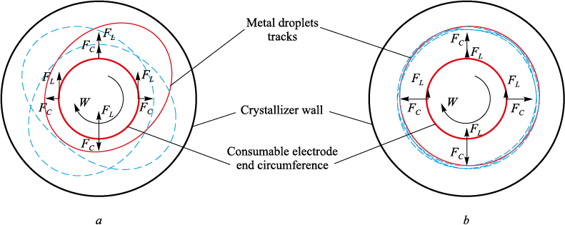
Both methods offer means to mitigate the effects of magnetic blowout. However, utilizing the consumable electrode’s rotation technology not only efficiently suppresses Ampere forces acting on the metal film and metal droplets during their transfer through the slag bath but also allows for tracking and controlling their trajectory within the slag bath and their landing on the metal bath surface. Fig. 1 presents a schematic diagram depicting the approximate trajectories of falling metal drops under two conditions: a stationary consumable electrode (or a consumable electrode rotating at an insufficient speed) and a rotating consumable electrode operating at an optimal speed.
Fig. 1. Metal droplets tracks and vectors of the acting forces: |
Fig. 1 illustrates that by using the impact of the consumable electrode’s rotation, it becomes feasible to efficiently mitigate the effect of magnetic blowout under any conditions while exercising control over the trajectories of falling metal drops. This control is achieved through the centrifugal force’s magnitude, which is directly reliant on both the rotation speed and the diameter of the consumable electrode.
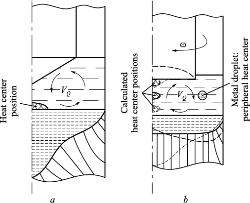
Addressing the energy efficiency concerns of a DC ESR furnace involves managing the positioning of the heat center and the associated heat release, adhering to the Joule–Lenz law. The utilization of direct current facilitates the polarization of charges within the slag bath, directly influencing the placement of the heat center. The intensity of Joule heat release correlates directly with the specific current density. Within the operational space of an ESR furnace’s slag bath, the specific electrical conductivity remains relatively consistent but varies proportionally with specific temperature. As metal droplets traverse the slag bath, they encounter regions of heightened electrical conductivity, momentarily creating branches of current flow. The refinement of droplets and their increased formation represent prerequisites for elevating the specific current density within the slag bath. Fig. 2 depicts a diagram illustrating the distribution of heat within a slag bath featuring both stationary and rotating consumable electrodes.
Fig. 2. Heat centers’ positions and directions of the convective fluxes |
In Fig. 2 illustrates that when employing direct polarity in direct current, the heat center within the slag bath resides at its interface with the metal bath. This displacement results in the formation of a pronounced meniscus within the resulting ingot, with its vertical extent expanding due to axial metal droplet transfer. Notably, for the sake of comparative clarity with the technology involving the rotation of the consumable electrode, the impact of magnetic blowout is not accounted for in this scenario. Under the rotation of the consumable electrode, active movement of the slag bath ensues, accompanied by reversed convective fluxes compared to the stationary method. The transfer of droplets shifts from the center to the periphery of the slag bath. This alteration, coupled with the revised direction of convective fluxes, modifies the shape of the crystallization front, resulting in a flatter metal bath. This alteration proves advantageous for the ingot’s crystal structure. As the consumable electrode’s rotation speed escalates, the intensity of droplet transfer and convective flux velocity increases. Consequently, these flows begin to wash the end of the consumable electrode upward along its axis. When combined with the direct current’s polarity, this phenomenon can effectuate the displacement of the heat center along the consumable electrode’s axis and within the ingot. However, surpassing critical values might lead to the formation of a concave end on the consumable electrode, diminishing droplet transfer intensity, enlarging droplet size, thereby creating an undesirable melting condition. Additionally, a peripheral meniscus in the metal bath might also form. Further insight into this issue, studied through physical simulation, is detailed in [9].
The determination of the effective current mode, coupled with the corresponding rotation mode of the consumable electrode, is achievable through the construction of a numerical model based on computational fluid dynamics principles. This approach has proven efficient in studying ESR, spanning from initial stationary problems [10; 11] to unsteady magnetohydrodynamic scenarios involving multiphase flow [12; 13]. The numerical simulation was conducted to analyze current distribution [14; 15] and the impact of external factors – such as the rotation of the consumable electrode – on melting speed [16; 17]. Additionally, electrochemical simulation concepts aimed at determining the resulting metal’s chemical homogeneity were developed [18 – 20].
The task of determining the amount of Joule heat released and localizing the heat center necessitates a combined approach to solving three subproblems: electrothermal, hydrodynamic, and convective. The electrothermal problem simulates direct current kinetics, adhering to the following fundamental law of the motion:
| \[\frac{{\partial j}}{{\partial \tau }} = - \nabla \varphi + \nabla (\sigma \nabla j),\] | (1) |
where j is the vector of specific current density, A/m; τ is the time step, s; \(\nabla\)φ is the gradient of electrical potentials’ difference, V; σ is the specific electrical conductivity of the environment, S.
The hydrodynamic problem is described by the Navier–Stokes transport equation:
| \[\frac{{\partial v}}{{\partial \tau }} + \nabla v(v) = - \nabla p + \nabla (\mu \nabla v) + {S_b} - {S_{sj}}v,\] | (2) |
where v is the specific speed vector, m/s; p is the specific hydrostatic pressure, Pa; μ is the kinematic viscosity of the environment, Pa·s; Sb is the Archimedes buoyant force, N; Ssj is the origin of crystallization/melting phenomena.
The problem of convective propagation and heat distribution is addressed through the energy transport equation:
| \[\frac{{\partial H}}{{\partial \tau }} + \nabla (\vec vH) = \nabla (\lambda \nabla t) + {q_{JH}} - \frac{{\partial \Delta H}}{{\partial \tau }},\] | (3) |
where H is the specific enthalpy, J; λ is the specific thermal conductivity, J/kg·K; qJH is the specific amount of heat released according to the Joule–Lenz law, J.
Results and discussion
Iterative calculations were carried out on a computational grid, representing a two-dimensional portrayal of a slag bath in a longitudinal section. To facilitate subsequent validation on an operational ESR furnace, the geometric dimensions corresponding to the consumable electrode and the water-cooled crystallizer were considered. The outer surface diameter of the consumable electrode is 60 mm, the internal diameter of the crystallizer is 90 mm, and the height of the subelectrode zone is set at 10 mm for enhanced result visualization. Given the relatively small length of the simulated area in comparison to the total length of the 590 mm water-cooled crystallizer, the inclination angle of the internal surface of the crystallizer (1.2°) was disregarded. During simulation, the current regime was set at 800 A and 46 V. The electrical conductivity of the environment was fixed at 120 S.
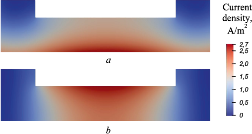
Post the iterative calculations on the established numerical model, output data was obtained and processed visually. This processing yielded information regarding the current kinetics in the slag bath and the temperature field. Figures displaying numerical fields of direct current kinetics are presented in Fig. 3.
Fig. 3. Numerical fields of current density distribution in slag bath |
Observations reveal that when melting using direct current of direct polarity is executed, the highest electric current density occurs above the surface of the metal bath. This density exhibits a gradient, declining from the center to the periphery and from the metal bath surface towards the consumable electrode surface. Conversely, the reverse pattern is evident in the image depicting reverse polarity, where the highest current density is observed at the end of the consumable electrode. Since Joule heat is released in regions of highest current density, its distribution reflects the pattern of the current density distribution. The silhouette of Joule heat mirrors the current density distribution pattern, as the equation determining the amount of Joule heat yields a scalar value derived from the absolute value modulus of the current density vector. Variations exist only in the absolute values of the numerical fields.
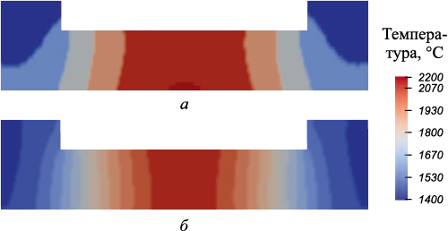
Fig. 4 depicts the temperature distribution diagram within the space of the slag bath.
Fig. 4. Numerical fields of temperature distribution in slag bath |
Under the application of direct polarity current, a gradual reduction in the temperature gradient is observable, extending from the center of the metal bath surface towards its periphery. This configuration highlights the hottest zone, represented as a concentrated spot at the center of the metal bath surface. The overall gradient exhibits a convex shape, tapering towards the end of the consumable electrode. However, in its vicinity, the temperature field expands somewhat, creating a distinctive hourglass shape with a lengthened lower part and a shortened upper section. A decline in temperature is evident as one approaches the periphery, particularly noticeable in the upper section of the crystallizer wall and the atmosphere – slag interface. Increased temperature at the slag-metal interface near the mold wall results from heightened current density arising due to the use of direct polarity. Upon examination of the temperature numerical field with reverse polarity current, the temperature gradient is similarly distributed from the central area towards the periphery. However, there is no evident localization of heightened current density foci akin to the direct polarity scenario. This lack of concentration could possibly stem from the smaller diameter of the consumable electrode relative to the metal bath, resulting in a reduced amount of released heat under reverse polarity. This decrease is attributed to a lesser amount of current flowing through a smaller diameter section, leading to reduced specific density. The longitudinal profile of the temperature gradient exhibits a concave shape, converging towards the surface of the metal bath but remaining nearly linear in its proximity, with a temperature drop evident towards the crystallizer wall. Here, the mold wall demonstrates higher efficiency in absorbing heat around the slag – metal interface due to the change in current direction. The vicinity surrounding the surface of the consumable electrode acts as a heightened heat source, causing relatively poorer heat removal at the atmosphere – slag interface compared to direct current polarity.
Quantitative data pertaining to current density and temperature characterizes the thermal distribution within the slag bath space, facilitating the prediction of furnace operating boundaries ranging from the complete absence of metal droplet transfer to the occurrence of jet metal transfer. Considering that the maximum temperature under direct polarity can reach 2200 °C above the metal bath’s surface, it becomes imperative to employ the rotation of a consumable electrode with a 60 mm diameter, within a speed range of 80 – 120 rpm. This selection aligns with empirical results obtained from experimental melts detailed in [3]. This rotational mode, in conjunction with the designated power of the ESR furnace, necessitates conditions ensuring enhanced efficiency while maintaining the maximum achievable melting speed without transitioning to jet metal transfer.
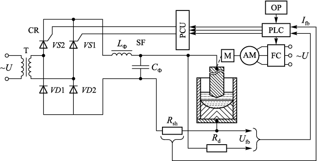
To further advance the technology and validate the numerical model, experimental melts are essential. Throughout the project, the existing A-550 ESR furnace underwent modernization, involving the automation of mechanical and electrical components and reconfiguration to operate using direct current. Fig. 5 depicts the functional diagram of the modernized furnace.
Fig. 5. Functional scheme for semi-industrial ESR furnace A-550 |
The furnace’s power supply system incorporates several key components, including a current regulator featuring a single-phase transformer (T), a controllable rectifier (CR), a phase pulse control unit (PCU), a smoothing filter (SF), a feedback loop on the current (Ifb ), сdetected via a resistive shunt (Rsh ), within the furnace power circuit, a control programmable logic controller (PLC), and an operator touch panel (OP). Furthermore, the automated furnace control system encompasses a slag pool voltage regulator, constructed around an electrode supply drive housing a transmission mechanism (M), an asynchronous squirrel-cage motor (AM), a transistor frequency converter (FC), a control programmable logic controller (PLC) that receives a feedback signal (Ufb), and an operator touch panel (OP).
Conclusions
A numerical model of an operating semi-industrial ESR furnace running on direct current of direct and reverse polarity has been developed. This model includes a computational grid, mathematical apparatus, an algorithm implemented on a computer, and a program code.
Iterative simulations were conducted, yielding results in the form of numerical fields that underwent post-processing for visualization purposes. These results clearly demonstrate the nature of the distribution of electric current and temperature in the slag bath. They do not contradict previously conducted research in this area and do not violate the laws of nature, which makes them valid for further application.
The acquired insights into temperature and current density distribution within the slag bath offer both qualitative and quantitative perspectives on the electrothermal processes occurring in this space. However, this model necessitates further development, particularly in incorporating the magnetic component of direct current, specifically the Lorentz force achieved through the rotation of the consumable electrode. Simulating this scenario, considering the magnetic aspect of the current, would require transitioning to a wave representation of electric current movement within a blend of electric and magnetic fields through their respective potentials.
The A-550 ESR furnace underwent modernization, involving the automation of its electrical and mechanical components and conversion to direct current for conducting experimental validation melts.
References
1. Pavlov V.A. Special Electrometallurgy of Steels and Alloys. Yekaterinburg: URFU; 2018:168. (In Russ.).
2. Seliverstov D.A., Pyatygin D.A., Chumanov I.V. To the issue of economic conversion feasibility of VAR furnaces to DC ESR furnaces. Izvestiya. Ferrous Metallurgy. 2007;50(1): 24–26. (In Russ.).
3. Pyatygin D.A., Chumanov I.V. Influence of current type and rotation speed of consumable electrode on mechanical properties of electroslag metal. Vestnik YuUrGU. Seriya: metallurgiya. 2011;14(231):40–44. (In Russ.).
4. Chumanov I.V., Pyatygin D.A. Influence of ponderomotive forces on the melt. In: Computer Modeling of Physicochemical Properties of Glasses and Melts. Proceedings of IX Russ. Seminar, October 14–17, 2008, Kurgan. Kurgan: Kurgan State University; 2008:64–65. (In Russ.).
5. Vinogradov V.S. Equipment and Technology of Automatic and Mechanized Arc Welding. Moscow: Academiya; 1997:319. (In Russ.).
6. Klyuev M.M., Volkov S.E. Electroslag Remelting. Moscow: Metallurgiya; 1984:208. (In Russ.).
7. Protokovilov I.V., Porokhon’ko V.B. Physical modeling of consumable electrode melting at ESR under external electromagnetic conditions. Sovremennaya electrometallurgiya. 2015;(1):8–12. (In Russ.).
8. Chumanov I.V., Pyatygin D.A., Roschin V.E. Features of electroslag process on direct current with electrode rotation. In: Modern Problems of Steel Electrometallurgy. Materials of XI Int. Conf., September 25–27, 2001, Chelyabinsk. Chelyabinsk: SUSU; 2001:117–118. (In Russ.).
9. Sergeyev D.V. Hollow billet production by electroslag remelting with single-electrode scheme: Cand. Tech. Sci. Diss. Chelyabinsk; 2022:126. (In Russ.).
10. Dilawari A.H., Szekely J. Heat transfer and fluid flow phenomena in electroslag refining. Metallurgical Transactions B. 1978;9B(2):77–87. https://doi.org/10.1007/BF02822674
11. Choudhary M., Szekely J., Medovar B.I., Yemel’yanenko Yu.G. The velocity field in the molten slag region of ESR systems: a comparison of measurements in a model system with theoretical predictions. Metallurgical Transactions B. 1978;13B(1):35–43. https://doi.org/10.1007/BF02666953
12. Kelkar K.M., Mok J., Patankar S.V., Mitchel A. Computational modeling of electroslag remelting processes. Journal de Physique IV. 2004;120:421–428.
13. https://doi.org/10.1051/jp4:2004120048
14. Kharicha A., Schutzenhofer W., Ludwig R., Tanzer R., Wu M. On the importance of electric currents flowing directly into the mould during an ESR process. Steel Research International. 2008;79(8):632–636. https://doi.org/10.1002/srin.200806176
15. Kharicha A., Karimi-Sibaki E., Wu M., Ludwig A. Contribution of the mold current to the ingot surface quality in the electroslag remelting process. In: The Minerals, Metals and Materials Society. Proceedings of the 2013 Int. Symp. on Liquid Metal Processing & Casting, September, 2013 TMS; 2013:95–99. https://doi.org/10.1002/9781118830857.ch13
16. Kharicha A., Wu M., Ludwig A., Karimi-Sebaki E. Simulation of the electric signal during the formation and departure of droplets in the electroslag remelting process. Metallurgical and Materials Transactions B. 2016;47(2):1427–1434. https://doi.org/10.1007/s11663-015-0550-4
17. Wang F., Wang Q., Lou Y., Chen R., Song Z., Li B. Investigation of heat transfer and magnetohydrodynamic flow in electroslag remelting furnace using vibrating electrode. JOM. 2015;68(1):410–420. https://doi.org/10.1007/s11837-015-1684-1
18. Wang Q., Gosselin L., Li B. Effect of rotating electrode of magnetohydrodynamic flow and heat transfer in electroslag remelting process. ISIJ International. 2014;54(12):2821–2830. https://doi.org/10.2355/isijinternational.54.2821
19. Karimi-Sibaki E., Kharicha A., Wu M. Toward modeling electrochemical reactions during electroslag remelting (ESR) process. Steel Research International. 2017;88(5):1700011. https://doi.org/10.1002/srin.201700011
20. Karimi-Sibaki E., Kharicha A., Wu M., Ludwig A., Bohacek J. A numerical investigation on the electrochemical behavior of CaO and Al2O3 in the ESR slags. Metallurgical and Materials Transactions B. 2020;51:871–879. https://doi.org/10.1007/s11663-020-01795-y
21. Wang Q., Li G., He Z., Li B. A three-phase comprehensive mathematical model of desulfurization in electroslag remelting process. Applied Thermal Engineering. 2017;114: 874–886. https://doi.org/10.1016/j.applthermaleng.2016.12.035
About the Authors
I. A. AlekseevRussian Federation
Ivan A. Alekseev, Postgraduate of the Chair “Pyrometallurgical and Foundry Technologies”
76 Lenina Ave., Chelyabinsk 454080, Russian Federation
I. V. Chumanov
Russian Federation
Il’ya V. Chumanov, Dr. Sci. (Eng.), Prof., Head of the Chair “Technique and Technology of Materials Production”
16 Turgeneva Str., Zlatoust, Chelyabinsk Region 456217, Russian Federation
D. V. Sergeev
Russian Federation
Dmitrii V. Sergeev, Cand. Sci. (Eng.), Engineer of the Chair “Technique and Technology of Materials Production”
16 Turgeneva Str., Zlatoust, Chelyabinsk Region 456217, Russian Federation
Review
For citations:
Alekseev I.A., Chumanov I.V., Sergeev D.V. Development of technology for ingots production using electroslag remelting at direct current with consumable electrode rotation. Izvestiya. Ferrous Metallurgy. 2023;66(5):623-630. https://doi.org/10.17073/0368-0797-2023-5-623-630


