Scroll to:
Investigation of electromagnetic furnaces with a C-shaped magnetic core
https://doi.org/10.17073/0368-0797-2023-4-492-497
Abstract
The paper describes design features, methodology and results of the study of 10 induction electromagnetic crucible furnaces with a C-shaped magnetic core (MC). The core is covered by turns of an electric coil (EC) of small volume up to ~14.56 dm3. The furnaces have MC from a set of used transformer plates with a working volume of ~ 28.5 – 30.8 dm3, a capacitor bank (CB), the number of turns w = 23 – 50 of copper or aluminum wire, voltage 380 – 390 V, frequency 50 Hz. The water-cooled EC is placed in a rubber tank and creates a horizontal electromagnetic flow with induction of ≈70 mT, which is amplified by MC and directed beyond EC into a larger working volume of ~30.7 dm3 between its poles with induction up to ≈100 mT. When placing a steel crucible in the volume, induction increases up to 125 – 150 mT and the experimental furnace EMC‑30.7‑23A with a capacity of 44 kVA allows melting 21 kg of silumin at a speed of 10 °C/min in 65 min, which is faster than in the resistance furnace СAT‑0.16 with a power of 40 kW in 2 h. With strong compression of MC plates, the noise decreases from 80 – 85 to 40 – 48 dB. To increase the furnace efficiency, it is proposed to use pole plates with a width of 155 mm, mineral wool in the thermal insulation of the crucible, tuning capacitors in CB, and EC from copper cable. For melting of high-temperature alloys, it is advisable to connect this furnace to a step-up transformer in order to increase the current density from 3.7 to the permissible 20 A/mm2, power in the EC – CB circuit, and EC induction. The authors suggest to continue research on electromagnetic furnaces made from cheap transformer scrap to determine the scope.
Keywords
For citations:
Levshin G.E. Investigation of electromagnetic furnaces with a C-shaped magnetic core. Izvestiya. Ferrous Metallurgy. 2023;66(4):492-497. https://doi.org/10.17073/0368-0797-2023-4-492-497
Introduction
There are two types of induction melting furnaces used in metal casting:
– a crucible inductor furnace creates a vertical electromagnetic flow and is commonly equipped with I-shaped outer сore-type open magnetic cores (MC);
– a channel furnace (transformer) with closed MC [1; 2].
In 2013, furnaces of the third type known as crucible induction electromagnetic furnaces, with curved O-, U- and C-shaped magnetic cores that create a horizontal working electromagnetic flow, were patented [3; 4]. These furnaces differ significantly in design, energy consumption, and process performance capabilities compared to the first type of furnaces. A comparison between inductor furnaces and electromagnetic crucible furnaces revealed several advantages of the latter [5; 6], which were further confirmed through investigations of the parameters and technology of melting aluminum and copper alloys in a U-shaped magnetic core electromagnetic furnace [7; 8].
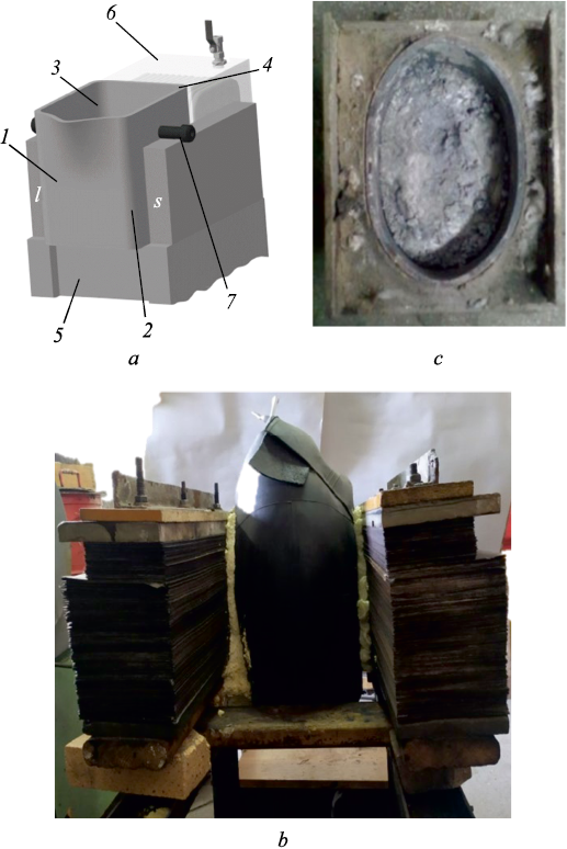
A similar investigation into the operation of a C-shaped MС design furnace, referred to as an EMC furnace, holds both scientific and practical significance. This EMC furnace features a horizontal open C-shaped MC 1 with two poles and core wrapped around by turns of an electric coil 4 (EC), incased in a protective sealed shell 6 for a cooling agent (Fig. 1, а). The magnetic core 1 forms the furnace shell, which can be permanently installed or equipped with a tilting mechanism. The electric coil 4 and magnetic core 1 collaborate to create intensive working flow between their facing poles, affecting the crucible 2 with its charge-containing bath 3, suspended on trunnions 7 or installed on a base 5 (Fig. 1, а) [3; 4]. The operational principles of this furnace are extensively described in [5; 6].
Fig. 1. Layout of electromagnetic furnace with a C-shaped |
No similar and detailed engineering solutions for induction melting crucible EMC furnaces, their operating parameters, and rational scope of application were discovered in the Google Scholar and Scopus databases [7 – 9]. Furthermore, they were not found on the websites of major induction melting furnace manufacturers1, 2, 3, 4, 5, 6, 7, 8, 9.
The objective of this paper is to investigate the design and operating parameters of EMC furnaces when melting silumin. This investigation aims to gather essential operational data necessary for design, calculation, and determining the rational scope of application.
The tests were conducted on ten manufactured furnaces10 (Fig. 1, b).
Investigation objects
The magnetic core of the furnaces is manually assembled utilizing used transformer plates with thickness of 0.35 and 0.40 mm. For pole heights hp of approximately 195 mm, wider plates measuring 175×615 mm are employed for the core, and 155×700 mm plates are used for the pole part. In order to increase hp to 240 mm maximize the effective volume Ve the furnaces were arranged in layers with an approximate height of 45 mm. In this configuration, plates measuring 55 mm, 90 mm or 120 mm in width are placed on the pole, while plates measuring 175 mm in width are used for the core. These plates are compressed using thick asbestos-cement and wooden spacers, belt ties, or steel studs insulated with electro-cardboard (Fig. 1, b). The pole length lwork in the range of 305 to 330 mm (hp /lwork ≈ 0.79).
The electric coil (EC) was manually wrapped around a dielectric frame using a stranded copper (C) flexible wire of the CF type with rubber insulation, having a cross-sectional area of approximately 78.5 mm2 and 130.0 mm2, or aluminum (А) wire with a 62 mm2 cross-sectional area and three layers of paper insulation. The length of the EC lec measured 2.8 dm, the door section was up to 5.2 dm2, and the cavity volume Vec was up to 4.56 dm3. The turns of the coil had either three or four bars, which were connected by a terminal at the EC outlets. To cool the EC, it was placed under running water, and a bundle of bars was inserted into a high-voltage-thermoplastic (HVT) tube to provide double electrical insulation. The EC itself was situated in a 13 dm3 tank. The section of the cross-sectional area and the number of turns took into account the conditions required to achieve a specific induction level and allowable heating of the EC when subjected to increased current, especially at voltages exceeding 390 V. The number of turns w for the EC included options like 28М, 30М, 37М, 50А, 40А, 30А or 23А. This choice had an impact on the length of the EC, and, therefore, on the length lw of the MC. The tank was placed inside a protective asbestos-cement shell, which also reduced the length lp of the poles of the MC and the working volume of the furnace Vw = hc lc lw , dm3 (here hw lw = Sw represents the working surface of the furnace pole).
The furnaces manufactured from transformer scrap were designed as EMC-Vр-w-M (or А):
– EMC-24.6-28М, EMS -24.6-37М,
– EMC-28.2-30М,
– EMC-28.7-23А,
– EMC-30.7-30А, EMC-30.7-40А, EMC-30.7-23А,
– EMC-30.8-28М, EMC-30.8-50А,
– EMC-35-50А.
Method of experiment
The service experience of the furnace with a U-shaped magnetic core was utilized [5; 6]. EMC furnaces were supplied with single-phase current Iec (f = 50 Hz) from the industrial grid at a voltage of U ≈ 380 ÷ 390 V. To explore the impact of the capacitor bank’s capacity СCB on furnace parameters, they were connected to the capacitor bank, and EС were connected in parallel. The СCB capacity was gradually increased by connecting old capacitor banks of KС2 and KМ2 type (GOST 1282 – 68) with a rated capacity of С = 80 ÷ 800 µF, with some variations in capacity. No tuning capacitors were employed to approximate current resonance in EC (Iec ) and CB (ICB ).
Steel cylindrical crucibles were used, with both round and oval sections, constructed from a heavy-wall (8 mm) tube with an outer diameter of 220 mm, along with an oxygen cylinder. These were housed within a portable asbestos-cement box featuring two types of thermal insulation: sand-clay-liquid glass mixture (Fig. 1, c); mineral wool combined with sheet asbestos.
The magnetomotive force (MMF) of EC Iecw, current density j, powers (total Sec ≈ SL – C, circulating in the L – C-circuit, active Р, and inductive QL ), total impedance Z and inductive reactance x, power factor cosφ, and electromagnetic induction Lem of the EMC furnace, active Iа and inductive IL currents were all computed based on electrical measurement results, employing electrical engineering formulas [5; 6; 10].
Integral criteria for energy intensity were also calculated, including magnetic Km = Iecw /Vw , electromagnetic Kem = Iecw/(ВеVр ), electric heating Keh = Sec/Ve , and power supply Keh = Sfeed /Vw [5; 6]. These criteria facilitate the comparison of various furnace parameters.
The temperature of a 21 kg silumin ingot AK7 was measured using a TRM-1 tool with a thermocouple XA enclosed in ceramic “beads”; temperature readings were recorded without applying scaling corrections. Temperatures of the top and bottom core surfaces of MC were measured using a multimeter M838 with thermocouples XA (without hoods). The temperature of the box walls, including the crucible and the skid, were measured using mercury thermometers.
The induction on the side and end surfaces of MC, both with and without the crucible, were measured at a distance from it and between the poles using a flat milliteslameter probe Sh1-15. Measurements were taken in three horizontal and seven vertical rows of points located 220 mm away from the ends of MC. To prevent potential damage to a Hall sensor due to rapid crucible heating, the probe was positioned up to 5 mm away from the right side of the crucible and the right pole. A DT-8851/52 tool, along with smartphones offered reliable reading proximity, was used to measure noise level.
Experiment result and discussion
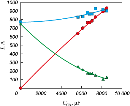
Results reflecting changes in the average values of feed currents Ifeed = Itot , as well as Iec and ICB , circulating in the EC – CB (L – C) circuit, depending on the capacity of СCB are presented in Fig. 2. The current Iec increases from 780 to 912 А, and the current ICB rises to around 920 А at an approximate СCB capacity of 8,134 µF (where these graphs intersect). What makes this particularly interesting is the decrease in the current Ifeed reducing from approximately 780 to 113 А at the same СCB capacity. This significantly lowers the power consumed from the circuit, transitioning from Sec = IfeedUfeed = 780·390 = 304,200 W up to Sfeed = 113·390 = 44,070 W (approximately a sevenfold reduction). Further reduction in power consumption can be achieved through the use of tuning capacitors.
Рис. 2. Dependence of currents of Icurrent ( |
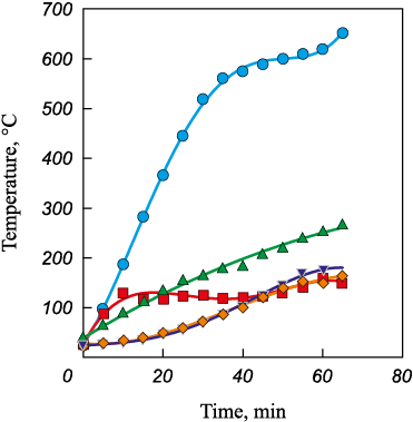
From experiments involving the heating and melting of a 21 kg silumin ingot in EMC furnaces equipped with a working volume Vw , EC, and crucibles, the most successful experience was observed in furnace EMC-30.7-23А featuring an oval crucible within a lining mix. This furnace achieved a silumin melting temperature of 650 °С within 65 min, with an average heating rate of 10 °С/min. High heating speed (14 – 19 °С/min) were maintained until the 30\(^{\rm{th}}\) min, reaching a temperature of 519 °C (Fig. 3). The heating speed decreased to 6 °С/min (reaching 560 °С), and then further to 3 °С/min. One of the reasons for this speed decrease is the heating of the box wall and increased heat loss outward. However, after the 60\(^{\rm{th}}\) min, the speed increased again to 6 °C/min due to overheating during melting.
Fig. 3. Dependence of temperature of ingot |
The core of MC is heated unevenly (Fig. 3). The lower surface, measuring 175 mm in width, reaches temperatures of approximately 160 °C as the melting process concludes, while the upper surface, characterized by narrow 120 mm plates intersecting, heats up to 268 °C. The increased heating in this section of the core can be attributed to the lower specific weight of the narrow plates.
Heating of the outer walls of the box remains nearly uniform and does not exceed 170 °С (Fig. 3). This temperature can be reduced by increasing the thickness (as space allows) or by using linings made from materials with low thermal conductivity, such as lightweight chamotte, mineral wool, and others. The steel crucible “burned out”, causing the melt to flow through cracks in the lining and the left wall of the box, emptying into the tank below the furnace at the end of the melting process. These cracks were formed due to recurring thermal deformations of the steel crucible, lining, and asbestos-cement walls. The top of the steel skid was heated by the leakage field to approximately 120 °С.
This heating of all elements contributed to the following performance parameters of the EMC-30.7-23А furnace (without the crucible):
– СCB ≈ 8,134 µF;
– Iec ≈ 911 А; ICB ≈ 893 А; Ifeed ≈ 113 А;
– SL – C ≈ 355 kV·А; Sfeed ≈ 44 kV·А; SL – C / Sfeed = 8;
– j ≈ 3.7 А/mm2;
– Z ≈ 0.428 Ω;
– Lem ≈ 0.001363 H;
– Iekw ≈ 20,953 А; Нc ≈ 74,800 А/m;
– Вcm = 94 mT; Вms = 47 mT; Вec = (Вcm + Вms )/2 ≈ 70 mT;
– Km ≈ 682.5 А/dm3;
– Kem ˃ 6.825 А/(dm3·mT);
– Ken ˃ 11.6 kV·А/dm3; Kec ˃ 1.43 kV·А/dm3.
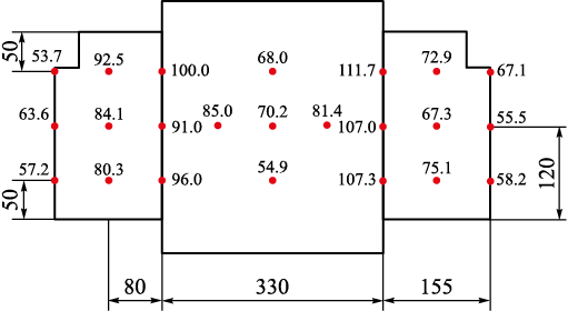
An analysis of the results of induction measurements on the surface of MC (with/without crucible) reveals the following (Fig. 4):
– expectedly increased induction Вd at the poles of the MC (91.0 – 111.2/125 – 150 mT);
– lower induction at the end faces of the MC (67.3 – 92.5/65 – 82 mT);
– lower induction at the outer surfaces of the MC (53.7 – 67.1/52 – 69 mT);
– the expectedly lowest induction is in the center between the poles (55 – 70 mT without crucible).
Fig. 4. Layout of points and results of induction measurement |
The distribution of induction Ве at the middle horizontal section points (Fig. 4) between the poles without the crucible (91 – 85 – 70 – 81.4 – 107 mT) reveals that the electromagnetic field is non-uniform and exhibits a horizontal gradient of 0.6 mT/mm directed from the center of lwork towards the poles.
The induction Вp is approximately 100 mT at the poles of MC, which significantly limits the volume Vw to approximately 30.7 dm3. This induction level greatly surpasses the induction in EC (Вek = 70 mT), despite EC having a much smaller volume Vec of approximately 14.56 dm3. This difference in induction is due to the magnetization of MC by the EC field. The induction of the leakage field of MC decreases rapidly with distance l following the equation Вdis ≈ 0.0012l2 – 0.6987l + 134.88.
When a steel crucible with a diameter of 220 mm is installed, the induction Вp at the poles and between the crucible and the poles has noticeably and expectedly increased (approximately 1.25 – 1.50 times). This can be explained by the presence of a ferromagnetic body with a diameter of 220 mm and two smaller gaps of 55 mm each within an open magnetic circuit with one larger air gap of length lwork = 330 mm. This configuration reduces the total magnetic resistance of the circuit and thus increases the induction at the poles. Such an increase in induction is highly beneficial when melting a ferromagnetic charge, as discussed in [11].
With the plates of MC being compressed more tightly, the noise level decreases at a distance of 600 mm from the furnace and 200 mm above EC, going from 80–85 dB (when compressed with belts) down to 40–48 dB (when compressed with pins). This signifies a substantial reduction in noise levels, decreasing from 80–85 dB to 40–48 dB with a strong compression of MC plates.
Выводы
The experimental furnace EMC-30.7-23А, with a capacity of 44 kW, enables the melting of 21 kg of silumin at a rate of 10 °C/min in just 65 min. In contrast, a resistance furnace СAT-0.16, with a power of 40 kW, requires 120 min to achieve the same result (at a rate of 5.4 °С/min).
To further improve the efficiency of heating and the operation of the furnace, it is advisable to increase the hp /lwork ratio from 0.79 to 1.0, broaden the pole plates to 155 mm, and incorporate mineral wool in the thermal insulation of the crucible. Additionally, tuning capacitors in CB and EC made from copper wire can be used.
Magnetizing the MC with a weak field at an induction level of Вec = 70 mT in EC, having a relatively small volume Vec of approximately 14.56 dm3, allows the field to be safely shifted beyond the limits of EC. This results in a notable increase in the induction Вp by around 100 mT within a significantly larger volume Vр (approximately 30.7 dm3). This reduction in EC size and electricity consumption, coupled with enhanced reliability, positively impacts the EC and overall furnace performance.
For testing the melting of copper alloys and cast iron, it is advisable to connect the furnace to a step-up transformer, which will increase the current density from 3.7 A/mm2 to the allowable 20 A/mm2. This increase significantly boosts the currents Iec , ICB , power SL – C, MMF Iecw, induction (Вec and Вp ), and enhances criteria such as Kem , Ken , Kec .
Building upon these successful experiences, it becomes feasible to create small-sized EMC furnaces from cost-effective transformer scrap. Further investigations can then be conducted to improve the parameters and determine their range of application, including heating charges, melting various types of alloys, holding and finishing molten materials, and facilitating the transfer of the crucible for casting purposes, among other applications.
References
1. Sakharevich A.N. Induction crucible furnaces. Design features, operation. Lit’e i metallurgiya. 2012;(3):242–245. (In Russ.).
2. Malyarov A.I. Foundry Furnaces. Moscow: Mashinostroenie; 2014:256. (In Russ.).
3. Levshin G.E., Sergeev S.Yu. Electromagnetic crucible melting furnace with C-shaped magnetic core and horizontal magnetic flux. Pat. RF 2536311. Byulleten’ izobretenii. 2014. (In Russ.).
4. Levshin G.E. Comparison of induction furnaces with vertical and horizontal electromagnetic flux. Metallurgiya mashinostroeniya. 2015;(5):2–6. (In Russ.).
5. Levshin G.E. Parameters of electromagnetic induction furnace with U-shaped magnetic core. Metallurgiya mashinostroeniya. 2017;(2):11–16. (In Russ.).
6. Levshin G.E. Electrotechnology of smelting in an electromagnetic furnace with U-shaped magnetic circuit. Elektrotekhnika. 2018;(5):73–76. (In Russ.).
7. Kachanov A.N., Kachanov N.A., Korenkov D.A. Classification and field of application of low-temperature induction heating systems with the opened magnetic conductors. Vestnik MEI. 2016;(2):36–40. (In Russ.).
8. Rudnev V., Loveless D., Cook R.L. Handbook of Induction Heating. New York: CRC Press; 2017:772. https://doi.org/10.1201/9781315117485
9. Lupi S. Fundamentals of Electroheat. Switzerland: Springer Int. Publ.; 2017:1–55.
10. Marchenko A.L., Opadchii Yu.F. Electrotechnics and Electronics. Vol. 1. Moscow: Infra-M; 2015:574. (In Russ.).
11. Levshin G.E. Magnetisation of ferromagnetic charge at induction heating. Izvestiya. Ferrous Metallurgy. 2022;65(2): 85–91. (In Russ.). https://doi.org/10.17073/0368-0797-2022-2-85-91
About the Author
G. E. LevshinRussian Federation
Gennadii E. Levshin, Dr. Sci. (Eng.), Prof. of the Chair of Engineering Technology and Equipment
46 Lenina Ave, Barnaul, Altai Territory 656038, Russian Federation
Review
For citations:
Levshin G.E. Investigation of electromagnetic furnaces with a C-shaped magnetic core. Izvestiya. Ferrous Metallurgy. 2023;66(4):492-497. https://doi.org/10.17073/0368-0797-2023-4-492-497
JATS XML


