Scroll to:
Electrospark deposition of metalloceramic Fe–Al/HfC coating on steel 1035
https://doi.org/10.17073/0368-0797-2023-3-302-310
Abstract
To improve the tribotechnical behavior and heat resistance of steel 1035, composite metalloceramic Fe–Al/HfC coatings were prepared by electrospark deposition. A non-localized anode was used as an electrode consisting of a mixture of iron and aluminum granules with a molar ratio of 3:2 and with the addition of HfC powder. The cathode gain had positive values indicating that HfC powder can be deposited on steel 1035 using the Fe60Al40 anode mixture. Moreover, the cathode gain monotonically increased with the increase in addition of HfC powder to the anode mixture. The coatings structure is represented by a matrix of FeAl intermetallic compound reinforced with HfC grains, which corresponds to the structure of a metalloceramic composite. Concentration of HfC in the coating increased with the addition of HfC powder to the anode mixture. Deposition of Fe–Al/HfC coatings according to the proposed technique allows reducing the friction coefficient of steel 1035 from 6 to 40 vol. %. Depending on the concentration of HfC in the anode mixture, the wear resistance of Fe–Al/HfC coatings varied nonmonotonically with a maximum at 8 vol. %. The use of Fe–Al/HfC coatings makes it possible to increase the wear resistance of the steel surface to 10 times. Comparison of the final weight gain of the samples after 100 h of oxidation resistance tests at a temperature of 700 °C allows us to conclude that electrospark deposition Fe–Al/HfC coatings can increase the oxidation resistance of steel 1035 by 1.7–2.2 times. Analysis of the study results shows that adhesion of Fe–Al composition to HfC is weak. This was reflected in decrease in hardness, wear resistance and oxidation resistance of coatings with an increase in the concentration of HfC in the anode mixture above 8 vol. %.
Keywords
For citations:
Burkov A.A., Kulik M.A. Electrospark deposition of metalloceramic Fe–Al/HfC coating on steel 1035. Izvestiya. Ferrous Metallurgy. 2023;66(3):302-310. https://doi.org/10.17073/0368-0797-2023-3-302-310
Introduction
Steel 1035 is a common structural material used for manufacturing such components as crankshafts, axles, connecting rods, spindles, sprockets, disks, pins, cams, pushrods, etc. [1]. It has such disadvantages as low wear, corrosion, and heat resistance which limits its applications [2]. Protective coatings can improve the heat, corrosion and wear resistance of medium-carbon steels [3; 4].
Metalloceramic matrix composites (MMC) are promising coating materials. They consist of a metal matrix reinforced with hard ceramic particles [5; 6].
Iron aluminides can be an efficient metal matrix in such coatings [7]. They have high heat (up to 1000 °C) and corrosion resistance in oxidizing and reducing environments, since the aluminum content is higher than in steels and heat-resistant alloys [8]. Yürektürk Y. et al. [9] report that Fe–Al coatings make steel component surfaces harder, and enhance wear and corrosion resistance. As noted by Pal M. et al. [10] The thermal expansion coefficient of iron aluminides matches that of most steel grades. For this reason, such coatings have high adhesion [10].
Hafnium carbide (HfC) is one of the hard-melting binary compounds. Toth L. et al. [11] reported that its melting point is 3928 °C. As noted by Hans K. et al. [12], HfС with high heat resistance is used in solar absorber coatings. Zang K. et al. [1] indicated that hafnium carbide is a highly suitable ceramic coating on steel substrates for its unique properties, such as high hardness, thermal and electrical conductivity and chemical stability [13]. For this reason, hafnium carbide can be used as reinforcement in MMC coatings. However, HfC coatings have poor heat resistance [14], since the crystalline hafnium carbide powder oxidizes at 430 °C and up [15]. Therefore, it is combined with a heat-resistant metal matrix to obtain high-temperature, wear-resistant coatings. The combination of solid hafnium carbide and heat-resistant Fe–Al matrix produces a successful MMC coating for steel 1035 parts operated at high temperatures.
We studied electrospark deposition (ESD) of HfC/Fe–Al coatings. It is a simple process with low requirements for the substrate surface finish. ESD results in metallurgical bonding between the coating and the substrate [16]. The authors also successfully applied a WC/Fe–Al coating to stainless steel using a modified electrospark deposition with a bulk electrode (EDBE). We used a bulk electrode made of Fe40Al60 pellets also containing tungsten carbide [7]. This composition was selected since the substrate iron is involved in the formation of the FeAl intermetallide. It was found that aluminum dominated over iron in the binder composition due to its lower melting point. Therefore, for the deposition of Fe–Al/HfC coatings, we used Fe40Al60 bulk electrodes with a lower aluminum content.
The purpose of this study is to analyze the effect of hafnium carbide powder content in a Fe40Al60 BE on the structure, wear, and heat resistance the of Fe–Al/HfC metal-ceramic electrodeposited coating on a steel 1035 substrate.
Materials and Methods
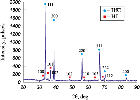
The substrates were diameter 12 mm, 10 mm high cylinders made of steel 1035. The bulk electrode was made of a mixture of iron and aluminum pellets, and varying amounts of hafnium carbide powder (99.6 % purity, 1.5 ± 0.5 µm average particle diameter). Refer to 1). The powder includes the HfC phase with a small admixture of hafnium metal (Fig. 1). The pellets were cylinders 4 ± 1 mm long cut off steel St3 and aluminum alloy 1188 bars, 4 ± 0.5 mm dia. The ratio of pellets in the BE was such that the iron-to-aluminum molar ratio was 3:2. The IMES-40 pulse generator produced rectangular current pulses, 110 A peak value, at 30 V with a 100 µs duration and a 1000 µs period. The substrate was connected to the negative lead of a pulse generator. A container with Fe60Al40 pellets and HfC powder was connected to the positive lead. The substrate was half-immersed into the pellet layer. See Burkov A. et al. [17] for a detailed description of the bulk electrode electrodeposition test bench. Argon was supplied into the container at a 5 l/min rate, in order to prevent oxidation. The pellets were pretreated, in order to saturate their surface with HfC powder for 10 min. The total coating application time was also 10 min.
Table 1. Composition of non-localized electrode
Fig. 1. X-ray diffraction pattern of HfC powder | |||||||||||||||||
The phase composition of the samples was studied using a DRON-7 X-ray diffractometer, CuKα band. We used PDWin software to identify the XRD patterns. The surface microrelief and elemental composition of the sample were analyzed with a Vega 3 LMH scanning electron microscope (SEM) (Tescan, Czech Republic) equipped with an X-max 80 energy dispersive X-ray spectrometer (Oxford Instruments) (EDS). The hardness was measured with a PMT-3M micro-hardness tester at 0.5 N (Vickers method). Wear resistance was tested according to ASTM G99-17 (dry sliding friction using) an R6M5 HSS disk counterbody sliding at 0.47 m/s under a 25 and 70 N load. At least three measurements were made for each sample. The wear was assessed by the gravimetric method with a 0.1 mg accuracy. The wear rate was estimated as
\[W = \frac{{\Delta m}}{{\rho Pl}},\]
where ∆m is the mass loss due to abrasion; ρ is the coating density assumed to be equal to the density of steel 1035; P is the load; l is the friction path length.
The samples were wear-tested after each weight measurement, in order to eliminate the error caused by a possible change in the counterbody surface properties. For heat resistance tests, the samples were placed in an oven at 700 °C. The total testing time was 100 h. The samples were held at this temperature for ~6 h, then removed from the oven and cooled to room temperature in a dryer. The samples were placed in a corundum crucible, in order to record the mass of the detached oxides. The sample weight changes were measured with lab scales, with 0.1 mg accuracy.
Results and Discussion
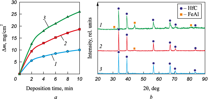
Studying the cathode weight evolution during electrospark deposition of new electrode materials is aimed at identifying cathode weight gain and the optimal treatment time. If the cathode loses weight, the process is inefficient. If the relative weight gain is low, the coating will be thin and non-continuous. The EDBE process generates electrical discharges between the steel pellets and the substrate, resulting in liquid metal transfer from the pellet surface to the substrate. Hafnium carbide powder particles occur on the surface of the electrodes at the time of discharge fuse with the metal. It leads to cathode weight gain (Fig. 2, a). After two minutes, the cathode weight gain rate slows down for all the bulk electrode materials. This can be explained by the accumulation of defects in the doped layer, and more intense electrical erosion as the number of discharges grows [18]. When the hafnium carbide concentration in the BE material increases from 4 to 12 vol. %, the cathode weight gain increases linearly from 9.96 to 26.1 mg/cm2. Such mass transfer can be explained by better conditions for electric discharges and higher discharge frequency with the increase of the HfC powder concentration in the granules. Previously we also observed a positive correlation between the powder concentration in the BE material and the cathode weight gain for Cr3C2 , TaC, and WC powders [19 – 21]. However, this relation can be inversed in other powders [22]. Therefore, further study of the powder composition and particle size distribution effects would be of interest.
Fig. 2. Cathode gain during electrospark deposition with a non-localized electrode (a) |
Fig. 2, b shows the XRD patterns of the coatings. The coatings contain hafnium carbide and intermetallic FeAl phases. This indicates that the coating has a ceramic-metal structure. The metal matrix is iron aluminide FeAl, and hafnium carbide is the reinforcing phase. The concentration of hafnium carbide in the coatings increases in a linear way with the powder content in the bulk electrode material. Note the XRD pattern of the Hf12 coating features only HfC reflexes.
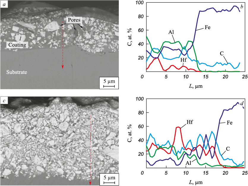
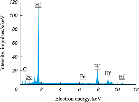
The average thickness of the coatings increases from 30.5 to 43.5 μm as the hafnium carbide powder content in the anode mixture increases (refer to Table 2), which agrees well with the measured cathode weight gain (Fig. 2, a). Figs. 3, a, c show the cross-sections of the Hf4 and Hf12 coatings. All the coatings have a biphasic structure: a dark gray matrix with white inclusions. According to the EDS analysis, the white inclusions are hafnium carbide (Fig. 4). The inclusion size in the HfC/Fe–Al coatings ranges from 0.2 to 7 μm. Figs. 3, a and c show that the HfC grain density increases with the hafnium carbide powder increase in the BE material, which agrees with the XRD analysis results. According to the EDS analysis results (Fig. 3, b, d), the concentration of aluminum in the coatings is higher than that of iron. As the iron-aluminum state diagram indicates, this ratio corresponds to the iron aluminide FeAl detected by XRD (Fig. 2, b). Therefore, the deposition of HfC powder mixed with iron and aluminum granules by the EDBE process creates a metal-ceramic structure through the introduction of ceramic particles into the metal matrix [23].
Table 2. Characteristics of the coatings
Fig. 3. Typical electron images of the cross section of coatings: Hf4 (a), Hf12 (c)
Fig. 4. EDS spectrum of section 1 at Fig. 3, а |
В структуре покрытий наблюдаются поры, возникновение которых при ЭИЛ принято объяснять испарением материала электродов в условиях высоких температур низковольтного электрического разряда [24]. Из-за высокой скорости охлаждения материала после окончания разряда газовый пузырь не успевает выйти на поверхность микрованны расплава. Вероятно, поэтому в ряде работ отмечается снижение порообразования с ростом энергии разрядов, сопровождающимся снижением скорости охлаждения материала [25; 26]. Средние значения шероховатости по критерию Ra были близки для всех покрытий и находились в узком диапазоне от 5,1 до 5,28 мкм (табл. 2).
The coatings are porous. The pore formation during ESD is usually attributed to the evaporation of the electrode material at high temperatures created by the low-voltage electric discharge [24]. Due to the high cooling rate after the discharge, the gas bubble does not have enough time to reach the surface of the melt. Several studies report that the porosity decreases with the discharge energy increase resulting in a reduced material cooling rate [25; 26]. The average Ra roughness values are similar for all the coatings and fall in a narrow range from 5.1 to 5.28 μm (Table 2).
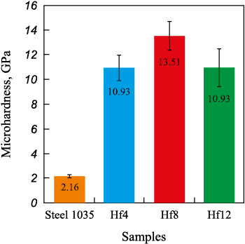
Fig. 5 shows the average microhardness values of the Fe–Al/HfC coatings. Note that the indentation diagonal at a 0.5 N load is at least 10 µm. This is significantly larger than the diameter of the HfC grains in the coating. The microhardness of the Fe–Al/HfC coatings ranges from 10.9 to 13.5 GPa, which is 400 – 500 % higher than that of steel 1035. Coating hardness varies in a non-linear way with the HfC powder content in the BE. The maximum value is observed in the Hf8 coating. The lower hardness of the Hf4 coating can be explained by its lower content of hafnium carbide (Fig. 2, b). On the other hand, the low hardness of the Hf12 coating can be attributed to the insufficient content of the Fe–Al bonding (Fig. 2, b). As a result, the HfC grains easily shift relative to each other when the diamond indenter is driven in
Fig. 5. Microhardness of the coatings and steel 1035 |
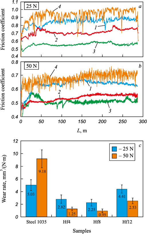
Fig. 6, a shows the friction coefficients of the coatings measured by wear tests (dry sliding) under 25 and 50 N loads. The average friction coefficient of the Fe–Al/HfC coatings ranges from 0.51 to 0.85: 6 to 40 % lower than that of steel 1035. Moreover, the wear tests of uncoated steel produced highly irregular friction coefficient curves. This can be explained by the periodic deposition and detachment of the material particles carried between the friction surfaces. Under both loads, the average friction coefficients of the coatings decrease linearly with the hafnium carbide content increase in the BE material due to the lower concentration of the ductile Fe–Al bond.
Fig. 6. Friction coefficient (а, b) and wear rate (c) of the coatings |
Fig. 6, b shows wear resistance test results. Coating wear rate ranges from (2.82 – 4.41)·10\(^{–}\)5 to (0.95 – 2.53)·10\(^{–}\)7 mm3/(N·m) under 25 and 50 N loads, respectively. The Hf8 coating has the lowest wear rate under both loads. This agrees well with the coating hardness values (Fig. 5) obtained with the Archard wear equation [27]:
\[{V_w} = k\frac{{Pl}}{H},\]
where Vw is the volume of wear debris produced; H is the material hardness; k is the wear factor; P is normal load; l is the sliding distance.
For the Hf4 sample, the low concentration of HfC grains and high friction coefficient leads to more extensive wear. With regard to the Hf12 coating, the low concentration of metal bonding cannot hold hafnium carbide grains, and the grains fall out. The wear rate of the coatings under a 50 N load is 72 to 89 % lower than that of steel 1035. The average coating wear rate under a 25 N load is slightly lower than that of steel 1035, and almost half as much under a 50 N load. This is probably caused by the steel 1035 surface hardening, when a 25 N friction load is applied. Therefore, the optimum concentration of hafnium carbide powder in the BE material is about 8 vol. %. In general, the wear rate values indicate a relatively low wear resistance of Fe–Al/HfC coatings. Note that our paper on Ti/HfC coatings [14] reports much lower wear rate values. This can be explained by the fact that the wettability of hafnium carbide with FeAl aluminide is lower than that of titanium. On the other hand, the wettability of tungsten carbide with FeAl aluminide is high [28].
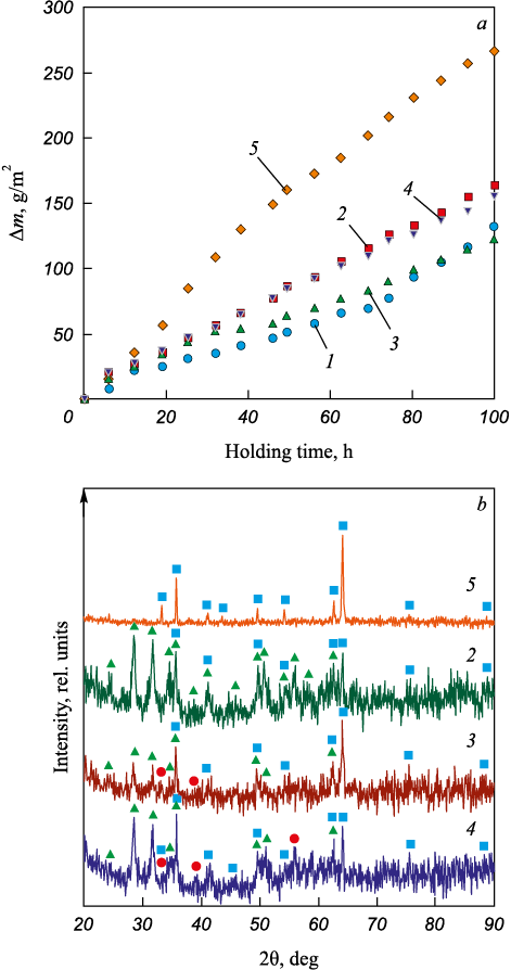
Fig. 7. Oxidation resistance of the samples at a temperature of 700 °C |
Fig. 7, a shows the results of cyclic heat resistance tests of the steel 1035 samples with Fe–Al/HfC coatings at 700 °C. After 100 h, the weight gain of the coated samples ranges from 123 to 164 g/m2. The weight gain is caused by oxygen fixation as iron oxide Fe2O3 as the hematite and hafnium dioxide HfO2 are modified (Fig. 7, b). The XRD patterns of the Hf8 and Hf12 coatings feature reflexes of hafnium carbide. It can be attributed to the protective effect of the Fe–Al matrix. However, this is unlikely due to weak Fe–Al to HfC adhesion. Furthremore, Musa C. et al. [29] showed that a compacted hafnium carbide-based material obtained by self-propagating high-temperature synthesis (SHS) followed by spark plasma sintering is resistant to oxidation at temperatures up to 750 – 800 °С. Luo H. et al. [30] reported that PVD coatings (HfC/a-C:H) begin to oxidize in the 500 to 600 °C temperature range. The HfO2 reflexes shown in Fig. 7, b indicate that the hafnium carbide was oxidized at 700 °C. In general, the oxidation start temperature in hafnium carbide-based materials strongly depends on the carbon content in HfC, the presence of impurities, and the share of the amorphous phase. The highest weight gain after 100 h of testing was observed in the Hf12 and Hf4 samples with the highest and lowest hafnium carbide contents, while the lowest gain was found in the Hf8 sample with an intermediate hafnium carbide content. For comparison, we tested a sample with Fe–Al, hafnium carbide-free coating. The weight gain was slightly higher than for the Hf8 sample. Reinforcing a Fe–Al matrix with hafnium carbide does not increase the heat resistance at 700 °C. The comparison of the sample weight gains in the samples indicates that electrospark deposition of Fe–Al/HfC coatings improves the heat resistance of steel 1035 at 700 °C by 70 – 120 %.
Conclusion
As the concentration of HfC powder in the anode material increases, the cathode weight gain and coating thickness increase in a linear way. The coating structure is a FeAl intermetallide matrix reinforced with hafnium carbide grains (a metal-ceramic composite). The hafnium carbide content in the coating increases with the HfC powder content in the anode material. The average friction coefficient values of Fe–Al/HfC coatings range from 0.51 to 0.85: 6 to 40 % lower than that of steel 1035. The dry sliding wear resistance of the coatings under a 50 N load is 260 – 860 % higher than that of steel 1035. Electrospark deposition of Fe–Al/HfC coatings improves the heat resistance of steel 1035 at 700 °C by 70 – 120 %. The decrease in hardness, wear, and heat resistance with the increase of HfC content in the anode material above 8 vol. % indicates low wettability and weak adhesion of Fe–Al to hafnium carbide.
References
1. Zang K., Chen W., Liang W., Miao Q., Yao W., Li J., Ma Y. Tribological behaviors of HfC coating prepared on 45 steel via double glow plasma surface metallurgy technique. Industrial Lubrication and Tribology. 2022;74(2):228–236. https://doi.org/10.1108/ILT-09-2021-0378
2. Gao W., Wang S.C., Hu K.K., Jiang X.Z., Yu H.Y., Sun D.B. Effect of laser cladding speed on microstructure and properties of titanium alloy coating on low carbon steel. Surface and Coatings Technology. 2022;451:129029. https://doi.org/10.1016/j.surfcoat.2022.129029
3. Bazhin P.M., Titov N.V., Zhidovich A.O., Avdeeva V., Kolomeichenko A.V., Stolin A.M. Features of the carbo-vibroarc surfacing in the development of multicomponent cermet wear-resistant coatings. Surface and Coatings Technology. 202;429:127952. https://doi.org/10.1016/j.surfcoat.2021.127952
4. Kumar A., Nayak S.K., Laha T. Comparative study on wear and corrosion behavior of plasma sprayed Fe73Cr2Si11B11C3 and Fe63Cr9P5B16C7 metallic glass composite coatings. Journal of Thermal Spray Technology. 2022;32:1302–1316. https://doi.org/10.1007/s11666-021-01280-1
5. Wang Y., Gao W. Microstructure and performance of Ni/TiN coatings deposited by laser melting deposition on 40Cr substrates. Coatings. 2022;12(3):367. https://doi.org/10.3390/coatings12030367
6. Torabinejad V., Rouhaghdam A.S., Aliofkhazraei M., Allahyarzadeh M.H. Ni–Fe–Al2O3 electrodeposited nanocomposite coating with functionally graded microstructure. Bulletin of Materials Science. 2016;39:857–864. https://doi.org/10.1007/s12034-016-1211-1
7. Burkov A.А. Bytsura A.Yu. Corrosion properties and tribological behavior of tungsten carbide coatings with aluminide matrix on SS AISI304. Fundamental’nye problemy sovremennogo materialovedenia. 2022;4(19):509–519. (In Russ.). https://doi.org/10.25712/ASTU.1811-1416.2022.04.010
8. Deevi S.C. Advanced intermetallic iron aluminide coatings for high temperature applications. Progress in Materials Science. 2021;118:100769. https://doi.org/10.1016/j.pmatsci.2020.100769
9. Yürektürk Y., Baydoğan M. Effect of aluminizing and austempering processes on structural, mechanical and wear properties of a SSF ductile iron. Materials Research Express. 2018;6(1):016550. https://doi.org/10.1088/2053-1591/aae804
10. Palm M., Stein F., Dehm G. Iron aluminides. Annual Review of Materials Research. 2019;49:297–326. https://doi.org/10.1146/annurev-matsci-070218-125911
11. Toth L.E. Transition Metal Carbides and Nitrides. Refractory Materials Series. Vol. 7. New York, London: Academic Press; 1971:91.
12. Hans K., Latha S., Bera P., Barshilia H.C. Hafnium carbide based solar absorber coatings with high spectral selectivity. Solar Energy Materials and Solar Cells. 2018;185:1–7. https://doi.org/10.1016/j.solmat.2018.05.005
13. Sciti D., Guicciardi S., Nygren M. Densification and mechanical behavior of HfC and HfB2 fabricated by spark plasma sintering. Journal of the American Ceramic Society. 2008;91(5):1433–1440. https://doi.org/10.1111/j.1551-2916.2007.02248.x
14. Burkov A.A. Improvement of Ti6Al4V-alloy wear resistance by electric-spark hafnium carbide coatings. Journal of Friction and Wear. 2020;41(6):543–548. https://doi.org/10.3103/S1068366620060045
15. Shimada S., Inagaki M., Matsui K. Oxidation kinetics of hafnium carbide in the temperature range of 480° to 600 °C. Journal of the American Ceramic Society. 1992;75(10): 2671–2678. https://doi.org/10.1111/j.1151-2916.1992.tb05487.x
16. Kudryashov A.E., Kiryukhantsev-Korneev P.V., Mukanov S.K., Petrzhik M.I., Levashov E.A. The effect of electrospark deposition using zirconium electrodes on structure and properties of nickel-containing alloy obtained selective laser melting. Powder Metallurgy and Functional Coatings. 2022;(3):63–77. (In Russ.). https://doi.org/10.17073/1997-308X-2022-3-63-77
17. Burkov A.A., Pyachin S.A. Formation of WC–Co coating by a novel technique of electrospark granules deposition. Materials & Design. 2015;80:109–115. https://doi.org/10.1016/j.matdes.2015.05.008
18. Nikolenko S.V., Syui N.A. Investigation of coatings produced by the electrospark machining method of steel 45 with electrodes based on carbides of tungsten and titanium. Protection of Metals and Physical Chemistry of Surfaces. 2017;53:889–894. https://doi.org/10.1134/S207020511705015X
19. Burkov A.A., Kulik M.A. Wear-resistant and anticorrosive coatings based on chrome carbide Cr7C3 obtained by electric spark deposition. Protection of Metals and Physical Chemistry of Surfaces. 2020;56:1217–1221. https://doi.org/10.1134/S2070205120060064
20. Burkov A.A., Krutikova V.O. Deposition of titanium silicide on stainless AI SI304 surface. Metal Working and Material Science. 2022;24(4):127–137. (In Russ.). https://doi.org/10.17212/1994-6309-2022-24.4-127-137
21. Burkov A.A., Kulik M.A., Krutikova V.O. Electrospark deposition of tungsten carbide powder on titanium alloy Ti6Al4V. Letters on Materials. 2021;11(2):175–180. (In Russ.). https://doi.org/10.22226/2410-3535-2021-2-175-180
22. Burkov A.A., Kulik M.A., Krutikova V.O. Characteristics of Ti–Si coatings on Ti6Al4V alloy subjected to electrospark granules. Tsvetnye Metally. 2019;4:54. (In Russ.). https://doi.org/10.17580/tsm.2019.04.07
23. Nurminen J., Näkki J., Vuoristo P. Microstructure and properties of hard and wear resistant MMC coatings deposited by laser cladding. International Journal of Refractory Metals and Hard Materials. 2009;27(2):472–478. https://doi.org/10.1016/J.IJRMHM.2008.10.008
24. Liu J., Wang R., Qian Y. The formation of a single-pulse electrospark deposition spot. Surface and Coatings Technology. 2005;200(7):2433–2437. https://doi.org/10.1016/j.surfcoat.2004.07.104
25. Shafyei H., Salehi M., Bahrami A. Fabrication, microstructural characterization and mechanical properties evaluation of Ti/TiB/TiB2 composite coatings deposited on Ti6Al4V alloy by electro-spark deposition method. Ceramics International. 2020;46(10A):15276–15284. https://doi.org/10.1016/j.ceramint.2020.03.068
26. Wang D., Deng S., Chen H., Chi C., Hu D., Wang W., He W., Liu X. Microstructure and properties of TiC particles planted on single crystal superalloy by electrospark discharging. Surface and Coatings Technology. 2023;461:129438. https://doi.org/10.1016/j.surfcoat.2023.129438
27. Greer A.L., Rutherford K.L., Hutchings I.M. Wear resistance of amorphous alloys and related materials. International Materials Reviews. 2002;47:87–112. https://doi.org/10.1179/095066001225001067
28. Karimi H., Hadi M. Effect of sintering techniques on the structure and dry sliding wear behavior of WC–FeAl composite. Ceramics International. 2020;46(11B):18487–18497. https://doi.org/10.1016/j.ceramint.2020.04.154
29. Musa C., Licheri R., Orrù R., Cao G., Balbo A., Zanotto F., Sani E. Optical characterization of hafnium boride and hafnium carbide-based ceramics for solar energy receivers. Solar Energy. 2018;169:111–119. https://doi.org/10.1016/j.solener.2018.04.036
30. Luo H., Sun H., Gao F., Billard A. Mechanical properties, thermal stability and oxidation resistance of HfC/a-C:H films deposited by HiPIMS. Journal of Alloys and Compounds. 2020;847:156538. https://doi.org/10.1016/j.jallcom.2020.156538
About the Authors
A. A. BurkovRussian Federation
Aleksandr A. Burkov, Cand. Sci. (Phys.-Math.), Senior Researcher, Head of the Laboratory of Physical and Chemical Foundations of Materials Technology
153 Tikhookeanskaya Str., Khabarovsk 680000, Russian Federation
M. A. Kulik
Russian Federation
Mariya A. Kulik, Junior Researcher
153 Tikhookeanskaya Str., Khabarovsk 680000, Russian Federation
Review
For citations:
Burkov A.A., Kulik M.A. Electrospark deposition of metalloceramic Fe–Al/HfC coating on steel 1035. Izvestiya. Ferrous Metallurgy. 2023;66(3):302-310. https://doi.org/10.17073/0368-0797-2023-3-302-310


