Scroll to:
Structure formation of Np-30KhGSA alloy in wire and arc additive manufacturing
https://doi.org/10.17073/0368-0797-2023-3-294-301
Abstract
The use of metallic products 3D-printing is a modern, promising technology that improves production efficiency. However, using this technology is associated with a number of problems, for example, with increased microstructural heterogeneity and defects in metal. Therefore, it is necessary to carry out researches to identify 3D-printing modes ensuring the most homogeneous, stable and non-defect structure. In this work, a study was made of the process of structure formation of 30KhGSA steel in the process of Wire and Arc Additive Manufacturing (WAAM) under various printing modes. Microstructural analysis, microhardness measurement and fractal analysis were used for assessment of the obtained billets. In all surfacing modes, a significant structural inhomogeneity of the deposited billet was revealed, which is explained by the thermal effect of the deposited layer on the already crystallized metal. Nevertheless, we found the mode that gives the most favorable microstructure in terms of its uniformity and equiaxed grains. With an increase in WAAM heat input values, an increase in the productivity of the process is observed and a decrease in the number of pores in the material is recorded. However, when the heat input of the surfacing process exceeds 1000 J/mm, the structural inhomogeneity of the material increases and its microhardness significantly decreases. Based on the studies, as a WAAM 3D-printing mode for Np-30KhGSA alloy, a mode with a heat input of about 920 J/mm can be chosen, which provides the lowest structural inhomogeneity and a sufficiently high productivity of the growth process with the absence of defects in the form of pores and elements of not melted wire.
For citations:
Anosov M.S., Shatagin D.A., Chernigin M.A., Mordovina Yu.S., Anosova E.S. Structure formation of Np-30KhGSA alloy in wire and arc additive manufacturing. Izvestiya. Ferrous Metallurgy. 2023;66(3):294-301. https://doi.org/10.17073/0368-0797-2023-3-294-301
Introduction
In contemporary manufacturing business, the rapid introduction of new products and optinal utilization of material are crucial requirements [1 – 2]. Wire or powder-based additive manufacturing is a method that can fulfill these requirement [3 – 4].
Numerous 3D-printing technologies exist, but in our assessment, Wire and Arc Additive Manufacturing (WAAM) holds significant promise due to its favorable productivity, low energy consumption, and superior mechanical properties compared to other 3D-printing processes [5 – 7].
Metal components produced through 3D-printing find extensive applications [8]. However, the limited knowledge concerning the structure, mechanical properties and chemical composition changes during 3D printing hampers their widespread adoption [9]. The geometry, chemical composition, and mechanical properties of the deposited material largely depend on the wire composition, 3D-printing conditions, and the duration of interlayer dwell time (thermal cycle properties). During 3D-printing, the newly deposited layer partially melts the previous layer, leading to changes in the structure of the unmelted metal below. Consequently, significant heterogeneity can arise across the thickness of the deposition layer. Fractal analysis, as proposed in papers [10 – 13], can be utilized to estimate this heterogeneity. Anisotropy in mechanical properties and residual stress can be minimized through mechanical or heat treatment [14 – 16].
The objective of this study is to examine the impact of WAAM conditions on the mechanical properties and formation of the metal structure.
Materials and Methods
We conducted a study on printed parts manufactured from the 30KhGSA alloy using a WAAM test bench [17]. The 30KhGSA alloy is widely employed for the production of robust components subjected to dynamic loads and/or high temperatures. Additionally, it finds application in repair welding, and surfacing processes [18]. The chemical composition of the wire is provided in Table 1.
Тable 1. Chemical composition of surfacing wire 30KhGSA
|
To manufacture the samples, we employed a computer-controlled WAAM process. Various printing conditions were deliberately modified, resulting in the creation of nine wall-shaped samples. Each sample was deposited in a single pass, with a width equivalent to the width of the deposited material. The samples consisted of ten layers in total, and the deposition of metal drops was accomplished through electric arc short circuits. During the WAAM process, a liquid metal drop is initially formed, and the end of the electrode is melted. Subsequently, the drop extends and closes the arc gap. The thin liquid bridge between the electrode and the drop evaporates rapidly due to its high resistance, causing the drop to explode and enters the weld pool. This sequence is repeated throughout the deposition process [19].
The surfacing mode variables include amperage (I, А), voltage (U, V), arc gap (z, mm), wire feed rate (V, mm/s) and shielding gas flow rate. For all the samples, we maintained a consistent arc gap of 11 mm and a wire feed rate of 200 mm/min, which were determined through preliminary testing. The shielding gas flow rate was not varied during the experiment.
Heat input (Q), measured in electric energy per unit of the weld length, was determing according to GOST R ISO 857-1-2009. An energy loss factor of 0.8 was assumed:
\[Q = \frac{{0.8IU}}{V}.\]
WAAM modes and corresponding heat inputs for each sample are provided in Table 2.
Тable 2. WAAM modes
|
To conduct microstructural analysis, samples were cut out from the deposited walls, reaching the same height as the printed walls. These samples were then polished using a polishing machine, followed by etching in a 4 % aqueous solution of nitric acid.
Chemical composition analysis was performed using a Foundry-Master optical emission analyzer with a sensitivity of approximately 0.001 %.
Microhardness evaluation was carried out using a Fischerscope HM2000 hardness tester. A square-based diamond pyramid indenter with an angle of α = 136 was employed. Microhardness measurements were conducted along the entire height of the deposited wall, applying a 50 g load. The load was held for 10 s, and the distance between adjacent hardness test points was 0.2 mm. Approximately five hardness measurements were taken in each area of interest, and the results were averaged.
Fractal analysis, as demonstrated by Gonchar et al. [20], was utilized to assess the surfacing microstructure and quality. Fractal dimension of the microstructure image was obtained through fractal analysis at different magnifications. A software package for this purpose was developed and registered under No. 2022666922 as the “Software for Microstructure And Structural Damage Assessment”.
To facilitate comparative analysis, measurements were conducted in three regions of interest: the base, middle, and top of the deposited metal wall.
Results and Discussion
In order to to assess the surfacing process efficiency, we measured the dimensions of the deposited walls and estimated the cross-section areas of the samples. The results of these measurements are presented in Table 3.
Тable 3. Geometric parameters of the billets obtained by 3D-printing
|
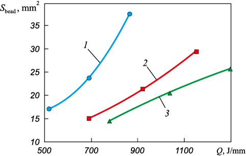
Fig. 1 illustrates the relationships between the cross-section area of the deposited layer (per one deposited bead) Sbead , and the heat input Q at different voltages values U.
Fig. 1. Dependence of cross-sectional area on the value |
These relationships clearly demonstrate the significant impact of input energy and deposition voltage on the speed of the 3D-printing process. For example, increasing the heat input at a constant voltage leads to a substantial and consistent increase in the process speed.
Figs. 2 – 4 depict micrographs of samples 1, 5 and 9, taken at cross-sections along the height of the deposited wall.
Fig. 2. Microstructure of the deposited wall near the substrate (a), in the center of the sample (b)
Fig. 3. Microstructure of the deposited wall near the substrate (a), in the center of the sample (b)
Fig. 4. Microstructure of the deposited wall near the substrate (a), in the center of the sample (b) |
The microstructure of the sample 1 wall near the substrate is predominantly composed of tempered bainite (Fig. 2, a). This structure formation can be attributed to the following factors.
• The relatively high cooling rate experienced by the layer in contact with the St3 (DIN analog: USt 37-2) steel grade substrate, which possesses a high thermal conductivity coefficient of 55 W/(m·K) at 20 °C. In comparison, the thermal conductivity coefficient for 30HGSA is 38 W/(m·K), while air has a coefficient of 0.0259 W/(m·K). Consequently, the cooling rate of the deposited metal is higher in contact with the substrate.
• The introduction of heat during the deposition of subsequent layers, leading to both quenching and tempering.
In the middle of the sample, the bainite structure is predominantly maintained, as shown in Fig. 2, b, However, other structural components, such as troostosorbite, are also noticeable. The cooling rate of this region after the deposition of a single layer is below the critical rate required for the diffusive decomposition of austenite. The energy input during the deposition of subsequent layers is sufficient for tempering as well.
The microstructure at the top of the sample differs from that at the base. It mainly consists of sorbite and ferrite. This structure can be explained by the following factors:
– cooling occurs in the air, which has a very low thermal conductivity coefficient (as mentioned above), without reaching critical cooling rates necessary for quenching;
– the absence of subsequent heat treatment that would induce phase recrystallization and temperin.
A chemical carbon liquation likely occurs in this region, evidenced by clear stripes (Fig. 2, c). The columnar grain structure is a result of heat dessipation as the deposited layer cools. Without subsequent heat treatment, the microstructure remains unchanged. It is important to noted that this region exhibits significant non-homogeneity in grain size, which can have adverse effects on the mechanical properties.
Proper heat treatment can eliminate the non-homogeneity in grain size and improve the microstructure.
Normalization or toughening can indeed be employed to address the non-homogeneity and improve the microstructure of the samples.
In the microstructure of sample 5, similar to sample 1, tempered bainite is observed near the substrate (Fig. 3, a). The structure transitions from bainite to troostosorbite in the middle, with the top layer consisting of sorbite. The transition between structures in this sample is smoother (Fig. 3, b). Importantly, all regions of this sample do not exhibit grain non-homogeneity or columnar grains in the last deposited layer (Fig. 3, c).
Sample 9 near the substrate displays a microstructure comprising tempered bainite with inclusions of other structures, such as troostosorbite. The microstructure in this region is generally coarser and more heterogeneous compared to other samples. However, the bainite gradually transforms into troostosorbite from the bottom to the middle of the sample. The middle of the sample contains larger grains compared to samples 1 and 5, likely due to the higher heat input during deposition (Fig. 4, b). The top layer of the sample consists of troostite and ferrite, with a highly heterogeneous microstructure across the sample section.
Through the microstructure analysis of the samples produced under different surfacing modes, it was determined that sample 5 (I = 160 A, U = 24 V, Q = 921.6 J/mm) possesses the most favorable metal structure. The micrographs of the samples did not reveal substantial structural defects commonly found in castings and welded parts, such as large pores or shrinkage cavities. However, micropores, grain non-homogeneity, and a heterogeneous structure were observed. These disadvantages can be mitigated through appropriate heat treatment. It is worth noting that all surfacing modes yielded fine-grained and highly dispersed structures.
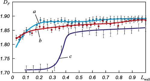
Furthermore, the DF fractal dimensions of the microstructures obtained under different WAAM conditions along the entire height of the deposited walls were estimated, excluding the first and last layers (machining allowance) (refer to Fig. 5). Variations in the fractal dimensions along the height of the deposited wall indicate significant structural changes, particularly in the sample manufactured at higher energy input.
Fig. 5. Dependence of the microstructural image fractal dimension |
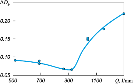
Fig. 6 illustrates the variations in the ΔDF fractional dimension, which contribute to the structural heterogeneity of the metal along the height of the sample.
Fig. 6. Spread of the fractal dimension values ΔDF of microstructural images |
The optimal heat input for achieving structural homogeneity along the wall height is approximately 900 J/mm. At lower heat input values, the structure becomes more heterogeneous, exhibiting a large number of pores and unmelted wire fragments, which is considered unacceptable. Conversely, higher heat input values result in significant heat transfer to the solidified and cooled metal, leading to microstructural changes such as phase recrystallization, hardening, and tempering. These changes cause the metal structure along the wall cross-section to become highly heterogeneous.
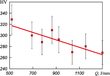
In order to assess the effects of surfacing modes on the material properties, microhardness measurements were conducted. Fig. 7 depicts the relationship between microhardness and heat input during the surfacing process.
Fig. 7. Dependence of 30KhGSA alloy microhardness |
As shown in Fig. 7, heat input has a notable impact on microhardness. With increasing heat input, the average microhardness decreases monotonically along the height of the sample. This phenomenon is primarily attributed to the elevated temperature in the fusion zone resulting from higher heat input. The increased temperature leads to the burning out of certain chemical elements, particularly carbon, and a subsequent loss of strength. The grain size experiences minimal changes, which is confirmed by the chemical analysis of the samples. For instance, as the heat input surpasses 900 J/mm, the carbon content in the alloy decreases from 0.3 % to 0.2 %, silicon decreases from 1 to 0.75 % and magnesium decreases from 1 % to 0.7 %.
The microhardness analysis also reveals the following: samples produced with a heat input of up to 900 J/mm exhibit relatively consistent microhardness along the entire height of the deposited wall. However, at higher heat input levels, the microhardness gradually increases from the base to the top of the sample, with more pronounced differences in the upper layers. The higher hardness observed in the top layers can be attributed to their shorter exposure to critical temperatures, preventing significant tempering from occurring.
Conclusions
This study determined that an optimal heat input of approximately 921.6 J/mm is suitable for the WAAM 3D-printing mode for Np-30KhGSA alloy. The specific conditions for achieving this optimal heat input are as follows: amperage of 160 A, voltage of 24 V, and a printing speed of 200 mm/min. The shielding gas used is a mixture of 80 % Ar and 20 % CO2 , delivered at a flow rate of 15 l/min. Under these optimized process conditions, the microstructure of the printed parts does not exhibit any pores or unmelted wire fragments, indicating a high level of material integrity. Additionally, the printing speed is considered sufficient, as indicated in Table 2, and the level of structural heterogeneity observed is insignificant, as demonstrated in Fig. 4).
References
1. Jackson M.A., Van Asten A., Morrow J.D., Min S., Pfefferkorn F.E. Energy consumption model for additive-subtractive manufacturing processes with case study. International Journal of Precision Engineering and Manufacturing-Green Technology. 2018;5(4):459–466. https://doi.org/10.1007/s40684-018-0049-y
2. Pinto-Lopera J.E., Motta J.M.S.T., Absi Alfaro S.C. Real-time measurement of width and height of weld beads in GMAW processes. Sensors. 2016;16(9):1500. https://doi.org/10.3390/s16091500
3. Li J.L.Z., Alkahari M.R., Rosli N.A.B., Hasan R., Sudin M.N., Ramli F.R. Review of wire arc additive manufacturing for 3D metal printing. International Journal of Automation Technology. 2019;13(3):346–353. https://doi.org/10.20965/ijat.2019.p0346
4. Kah P., Latifi H., Suoranta R., Martikainen J., Pirinen M. Usability of arc types in industrial welding. International Journal of Mechanical and Materials Engineering. 2014;9:15. https://doi.org/10.1186/s40712-014-0015-6
5. Ding D., Pan Z., Cuiuri D., Li H. Wire-feed additive manufacturing of metal components: technologies, developments and future interests. The International Journal of Advanced Manufacturing Technology. 2015;81:465–481. https://doi.org/10.1007/s00170-015-7077-3
6. Wu B., Pan Z., Ding D., Cuiuri D., Li H., Xu J., Norrish J. A review of the wire arc additive manufacturing of metals: Properties, defects and quality improvement. Journal of Manufacturing Processes. 2018;35:127–139. https://doi.org/10.1016/j.jmapro.2018.08.001
7. Anosov M.S., Shatagin D.A., Mikhailov A.M., Andronov D.V. Rationale for the use of 3D-printing technology by electric arc welding to obtain parts in small-scale production. Actual Problems of Science and Education in the Context of Modern Challenges: Proceedings of the XIII Int. Sci. and Prac. Conf., Moscow, August 15, 2022. Moscow: Pechatnyi tsekh; 2022:291–295. (In Russ.).
8. Kudryashov V.A., Lapyshev A.A. Creation of additive technologies according to fatigue behaviour of material in aviation engineering. Izvestiya Samarskogo nauchnogo tsentra Rossiiskoi akademii nauk. 2018;20(4–3(84)):406–413. (In Russ.).
9. Kubanova A.N., Sergeev A.N., Dobrovol’skii N.M., Gvozdev A.E., Medvedev P.N., Maliy D.V. Materials and technologies for production products by additive manufacturing. Chebyshevskii Sbornik. 2019;20(3):453–477. (In Russ.). https://doi.org/10.22405/2226-8383-2019-20-3-453-477
10. Garashchenko Y., Glushko A., Kobets O., Harashchenko O. Fractal analysis of structural and phase changes in the metal of welded steam pipe joints. Advances in Design, Simulation and Manufacturing IV. DSMIE 2021. Lecture Notes in Mechanical Engineering. https://doi.org/10.1007/978-3-030-77719-7_4
11. Krasikova I.E., Krasikov I.V., Kartuzov V.V. Correlation of fractal characteristics of the material structure by electron-microscopic images of the sample surface with their physical and mechanical properties Elektronnaya mikroskopiya i prochnost’ materialov. Seriya: Fizicheskoe materialovedenie, struktura i svoistva materialov, 2016;(22):3–9. (In Russ.).
12. Zaiser M., Bay K., Hähner P. Fractal analysis of deformation-induced dislocation patterns. Acta Materialia. 1999;47(8):2463–2476. https://doi.org/10.1016/S1359-6454(99)00096-8
13. Kabaldin Y.G., Anosov M.S., Shatagin D.A. Evaluation of the mechanism of the destruction of metals based on approaches of artificial intelligence and fractal analysis. IOP Conference Series: Materials Science and Engineering. 2020;709:033076. https://doi.org/10.1088/1757-899X/709/3/033076
14. Rodrigues T.A, Duarte V., Miranda R.M., Santos T.G., Oliveira J.P. Current status and perspectives on wire and arc additive manufacturing (WAAM). Materials (Basel). 2019;12(7):1121. https://doi.org/10.3390/ma12071121
15. Bai X., Zhang H., Wang G. Modeling of the moving induction heating used as secondary heat source in weld-based additive manufacturing. The International Journal of Advanced Manufacturing Technology. 2015;77:717–727. https://doi.org/10.1007/s00170-014-6475-2
16. Donoghue J., Antonysamy A.A., Martina F., Colegrove P.A., Williams S.W., Prangnell P.B. The effectiveness of combining rolling deformation with Wire–Arc Additive Manufacture on β-grain refinement and texture modification in Ti–6Al–4V. Materials Characterization. 2016;114:103–114. https://doi.org/10.1016/j.matchar.2016.02.001
17. Kabaldin Yu.G., Shatagin D.A., Anosov M.S., Kolchin P.V., Kiselev A.V. Diagnostics of 3D-printing on a CNC machine using machine learning approaches. Vestnik mashinostroeniya. 2021;(1):55–59. (In Russ.). https://doi.org/10.36652/0042-4633-2021-1-55-59
18. Chinakhov D.A. Research and development of technology for welding multilayer joints from 30KhGSA steel, providing guaranteed quality of welded joints with minimal resource and labor costs. Sovremennye naukoemkie tekhnologii. 2006;(3):73–75. (In Russ.).
19. Atroshchenko V.V., Tefanov V.N., Kraev K.A. On control of metal transfer during welding by consumable electrode with a short circuit of arc interval. Vestnik Ufimskogo gosudarstvennogo aviatsionnogo tekhnicheskogo universiteta. 2008;11(2):146–154.
20. Gonchar A.V., Kurashkin K.V., Andreeva O.V., Anosov M.S., Klyushnikov V.A. Fatigue life prediction of structural steel using acoustic birefringence and characteristics of persistent slip bands. Fatigue & Fracture of Engineering Materials & Structures. 2022;45(1):101–112. https://doi.org/10.1111/ffe.13586
About the Authors
M. S. AnosovRussian Federation
Maksim S. Anosov, Cand. Sci. (Eng.), Assist. Prof. of the Chair “Technology and Equipment Engineering”
24 Minina Str., Nizhny Novgorod 603022, Russian Federation
D. A. Shatagin
Russian Federation
Dmitrii A. Shatagin, Cand. Sci. (Eng.), Assist. Prof. of the Chair “Technology and Equipment Engineering”
24 Minina Str., Nizhny Novgorod 603022, Russian Federation
M. A. Chernigin
Russian Federation
Mikhail A. Chernigin, Engineer
24 Minina Str., Nizhny Novgorod 603022, Russian Federation
Yu. S. Mordovina
Russian Federation
Yuliya S. Mordovina, Academic Activity Engineer
24 Minina Str., Nizhny Novgorod 603022, Russian Federation
E. S. Anosova
Russian Federation
Ekaterina S. Anosova, Assistant
24 Minina Str., Nizhny Novgorod 603022, Russian Federation
Review
For citations:
Anosov M.S., Shatagin D.A., Chernigin M.A., Mordovina Yu.S., Anosova E.S. Structure formation of Np-30KhGSA alloy in wire and arc additive manufacturing. Izvestiya. Ferrous Metallurgy. 2023;66(3):294-301. https://doi.org/10.17073/0368-0797-2023-3-294-301


