Scroll to:
Degree and depth of hardening under pendulum surface plastic deformation of carbon steel
https://doi.org/10.17073/0368-0797-2023-3-272-282
Abstract
The article discusses influence of the main technological parameters of pendulum surface plastic deformation (SPD) on the mechanical properties of surface layer of cylindrical parts made of carbon steel. Using the hardness tester HBRV-187.5 and the microhardness tester HMV-G21, we determined hardness of the surface layer, microhardness and depth of the work-hardened layer of hardened parts. In addition, the results of calculating the hardening degree are presented, which is important information for evaluating the effectiveness of SPD method in terms of improving the metal mechanical properties. Experimental studies showed that after pendulum SPD (at different processing modes), hardness of the surface layer increases by 9 – 12 % compared to hardness of the original surface, and the microhardness increases by 1.5 – 1.7 times, which leads to a significant hardening of the cylindrical billet surface layer. Depth of the hardened layer varies in the range of 0.9 – 1.1 mm, while the hardening degree is 45 – 65 %. Using the software package Statistica 10.1, which allows solving optimization problems based on statistical analysis and building an optimization model, we determined the optimal modes of hardening by pendulum SPD. These modes simultaneously provide both the maximum depth of the hardened layer and the highest hardening degree of the surface layer. They are formed under the following processing modes: radial interference t = 0.15 – 0.2 mm; longitudinal feed s = 0.07 – 0.11 mm/rev; billet rotation frequency nb = 160 – 200 min−1; frequency of the working tool pendulum movement nt = 110 – 130 strokes/min; angular amplitude of the working tool α = 35 – 40°. According to the results of experimental data and numerical calculations, it was established that the average grain size in pendulum SPD decreases by 30 – 40 % compared to the initial size, and the dislocation density increases by 2.5 times.
Keywords
For citations:
Zaides S.A., Quan H.M. Degree and depth of hardening under pendulum surface plastic deformation of carbon steel. Izvestiya. Ferrous Metallurgy. 2023;66(3):272-282. https://doi.org/10.17073/0368-0797-2023-3-272-282
Introduction
The reliability of mechanical products largely depends on the quality of their components. This quality encompasses not only the dimensional accuracy and surface finish of the parts but also the mechanical properties of the surface layer exposed to various loads and thermal effects. Reliability can be enhanced through better materials, design, manufacturing, and operational practices. As indicated in references [1 – 3], improvements in the manufacturing process yield the most favorable outcomes.
In order to enhance the performance characteristics of the surface layer of machine parts, the technology of finishing-hardening treatment through surface plastic deformation (SPD) treatments are extensively employed [4 – 6].
Plastic deformation alters the structure of the metal surface layer. It significantly increases the number of dislocations, vacancies, and other defects in the lattice. Grains are fragmented and clustered, leading to changes in the size and shape of grains within the surface layer. Elastoplastic deformation resulting from machining alters the physical and chemical properties of the metal surface layer [7 – 9].
Plastic deformation induces hardness in the metal, with hardness diminishing linearly with depth. For example, Mitrofanova K. et al. [10] reported that parts made from grade 45 steel, after spinning with a variable-radius roller tool, possess a hardened layer approximately 1.1 mm deep. The microhardness within the region of plastic deformation remains relatively low, at approximately HV. Smoothing grade 45 steel components with a diamond tool leads to a tenfold increase in tangential stress. The depth of the hardened layer ranges from 0.05 to 0.40 mm (as the smoothing force escalates from 50 to 200 N). The dislocation density within the hardened surface layer signifies the extent of grain refinement, witnessing an increase of 40 to 70 % [11].
Metal hardening through surface plastic deformation enhances the parts’ performance by increasing wear resistance, contact strength, and reliability of the press fits [12 – 14].
The key surface quality indicators are hardness and the depth of the hardened layer [15 – 17]. The extent of hardening depth correlates with roller pressure and can influence various surface layer properties. Deeper hardening improves wear resistance, while in terms of fatigue strength, studies [2; 11; 15; 18] suggest that residual compressive stresses decrease as hardening depth increases, which maight reduce durability gain.
Significant contributions to analytically estimating hardening depth through SPD have been made by researchers such as Braslavsky V.M., Drozd M.S., Kudryatsev I.V., Matlin M.M., Petushkov G.E. and Heifetz S.G. However, the existing relationships are only applicable to basic forming operations.
Researchers at Irkutsk National Research Technical University have refined surface plastic deformation processes by utilizing more intricate tool motions. The introduced a mechanical hardening process involving a swinging (pendulum) motion of the tool [19]. This process alternates between rolling and sliding actions. In our own work [20], we’ve assessed the stress increase within the deformation area achievable without raising the radial tool interference and residual stress [20].
This study aims to discern the impact of variables related to the swinging tool deformation on hardening depth and final hardness, while also evaluating the feasibility of the process.
Materials and Methods
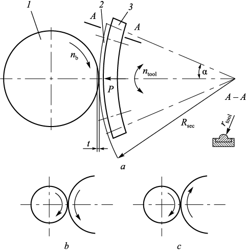
Fig. 1 illustrates the pendulum tool treatment process. In this process, denoted as Pendulum Tool Plastic Deformation (PTPD), the outer surface 1 is rotated about its centerline. The tool is pressed onto the surface and moved with a radial interference t. The tool is advanced parallel to the part axis. The tool itself takes on the form of a sector 3 with a circular surface 2. This sector-shaped tool is firmly attached to a rocker that oscillates within the α angle range.
Fig. 1. Scheme of pendulum surface plastic deformation (а): |
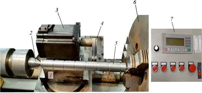
For the experiments, we utilized a 1K62 lathe. The upper carriage was replaced with the sector-shaped tool drive (Fig. 2). The tool’s specifications include a sector radius Rsec = 65 mm; an edge fillet radius rtool = 3 mm; and it’s made of R18 HSS material. The lubricant used was I-40A industrial oil, commonly employed in hardening processes.
Fig. 2. General view of the device for pendulum surface plastic deformation (SPD) |
We machined cylindrical samples with a 25 mm diameter, using medium-carbon steel grade 45 and measured the resulting hardening depth and final hardness. These samples were designed with six equally spaced grooves to demarcate six segments of the same length and diameter. We tailored the process variables to treat conducting tests for five different sets of variables per sample. Each set of process variables was applied to three samples, and the curves illustrate the mean values.
In order to eliminate any runout, the sample was clamped within the three-jaw chuck of the lathe and additionally supported by the tailstock center. The cylindrical surface of the sample was machined to a 25 mm diameter (with parameters s = 0.17 mm/rev, rpm = 620, t = 0.5 mm) and subsequently subjected to hardening via plastic deformation.
Before conducting the tests, we performed hardening on a pilot batch of samples to establish the baseline plastic deformation mode. The foundational process variables were determined as follows: radial interference t = 0.07 mm; longitudinal feed s = 0.07 mm/rev; billet rotation frequency nb = 100 rpm; tool angular amplitude α = ±20°; and tool frequency ntool = 55 double strokes/min.
After the hardening process using the pendulum tool, the cylindrical samples were slice into thin sections utilizing a Discotom-10 metallographic cutting machine. These sections were then positioned within molds and filled with Aka-Resin Acrylic epoxy resin powder, subsequently compressed on a POLYLAB S50A automatic press. Following this, the sample sections underwent grinding and polishing on a Tegramin-25 automatic grinding and polishing machine, employing water cooling to achieve a mirror-like shine. In order to reveal the microstructure, the thin sections of the steel grade 45 samples were subjected to etching using a solution of 5 % nitric acid (HNO3) mixed with alcohol.
The Rockwell hardness of the surface layer was measured using an HBRV-187.5 hardness tester. For each segment of the sample, hardness was measured at six distinct points, situated on two circumferences. The hardness value for each segment was determined as the average of these six measurements.
Microhardness measurements were conducted using an HMV-G21 microhardness meter, adhering to GOST R ISO 6507-1-2007 standards. The instrument employed a diamond Vickers pyramid penetrator to indent a flat section of the sample. The HV0.2 scale was employed, with a rated load of 1.961 N and a holding time of 5 s. Microhardness readings were taken at three points evenly spaced around the circumference. Mean hardness values were computed and microhardness vs. process variable curves were plotted for each process variable (as shown in the curves below).
The microstructure of the hardened samples was examined using a MET-2 metallographic microscope. A ×500 magnification of the metal’s structure was observed on a computer screen utilizing the ToupView software. The grain size was estimated as the mean of the maximum and minimum grain dimensions. Obtaining consistent results with minimal error required 5 to 7 measurements, and at least 10 measurements were taken for each grain.
Experimental Results
Let us examine the essential physical and mechanical properties of the hardened surface, such as surface layer hardness, microhardness and hardening depth, and their correlations with the process variables within the pendulum tool treatment process.
Surface Layer Hardness. In Table 1, we present the surface hardness values following the pendulum tool treatment in relation to the key process variables.
Table 1. Hardness of the surface layer of cylindrical parts
|
Based on the available experimental outcomes, it is evident that the surface layer hardness experiences an average increase of 9 to 12 %. Notably, the process variables with substantial impact on hardness augmentation include radial interference, longitudinal feed, billet rotation frequency rpm, pendulum frequency, and the amplitude of angular tool movement.
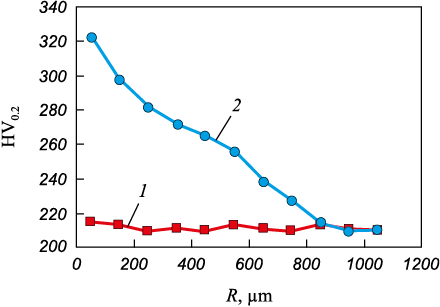
Microhardness of the Hardened Layer. Microhardness measurements provide insights into both absolute hardness and the depth of hardening. As depicted in Fig. 3, the distribution of microhardness across the cross-section of the hardened part (under the baseline process mode) is showcased. Notably, the initial microhardness of the sample after turning ranged between 210 to 215 HV0.2 . Subsequent to the pendulum tool treatment, microhardness at a depth of 50 μm beneath the surface surged to 320 HV0.2 .
Fig. 3. Distribution of microhardness over the surface layer depth |
It should be noted that the microhardness decreases towards the centerline of the cylindrical part. At a certain depth, it becomes equal to the initial microhardness of the part metal. The increased depth of the microhardness layer is approximately 0.88 mm (Fig. 3). Fig. 3 illustrates the distribution of microhardness across the depth of the hardened layer.
Table 2 outlines the relationships between the key process variables, maximum microhardness and hardening depth.
Table 2. Microhardness (HV0,2 ) on the surface and hardening depth (h)
|
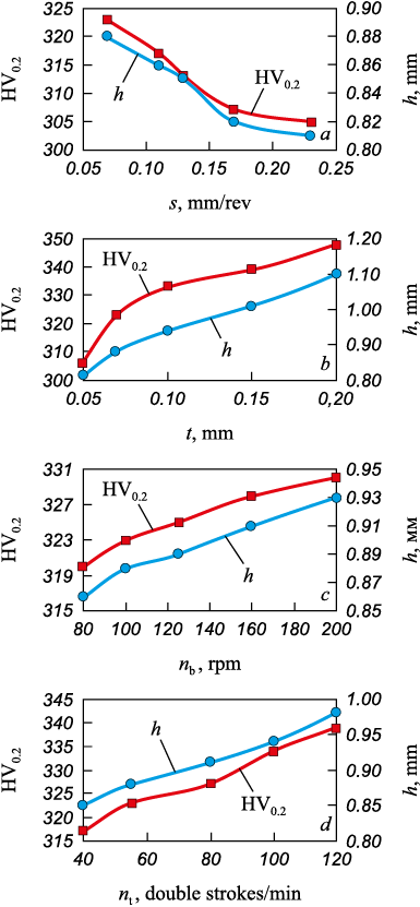
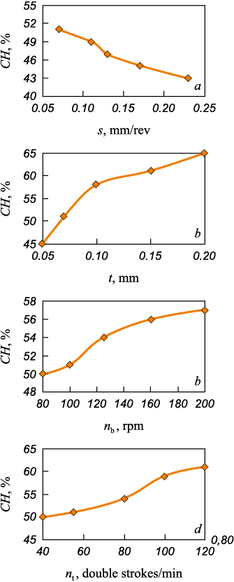
Fig. 4 displays the curves of microhardness and hardening depth against the key process variables (s, t, nb , ntool ) curves.
Fig. 4. Dependence of microhardness and hardening depth |
The study revealed that as the radial interference increases from 0.05 to 0.20 mm, the microhardness of the surface layer increases by approximately 12 %, whereas the increase in hardening depth is approximately 35 %. With an increase in longitudinal feed from 0.07 to 0.23 mm/rev, there is a decreases in microhardness by 3 to 5 % and a decreases in hardening depth by 7 to 8 %. Furthermore, elevating the billet rotation frequency RPM (from 80 to 200) and the frequency of the pendulum tool (from 40 to 120 double strokes per min) also results in a microhardness increase of 10 to 14 % and an increase in hardening depth by 15 to 18 %. The variation in angular amplitude has minimal effect on microhardness and hardening depth.
The rate of hardening (СН) in the surface layer after plastic deformation can be estimated using the following equation:
| \[CH = \frac{{H{V_2} - H{V_1}}}{{H{V_1}}} \cdot 100{\rm{ }}\% ;\] | (1) |
where HV1 represents the initial microhardness of the surface layer; HV2 is the microhardness after treatment.
Table 3 presents the estimated hardness values in relation to the key process variables.
Table 3. Influence of the main parameters of pendulum SPD on hardening degree
|
The data suggest that under baseline conditions, the hardening rate is approximately 50 %. By adjusting the process variables, the hardening rate can be varied within the range of 45 to 65 %. Fig. 5 illustrates the curves depicting the relationship between hardening rate and key process variables (s, t, nb , ntool ).
Fig. 5. Dependence of hardening degree |
To determine the optimal treatment mode for pendulum tool, with the aim of achieving the maximum depth of the hardened layer and hardening rate, we utilized the Statistica 10.1 software package. This software is extensively employed for statistical analysis within the manufacturing field. Utilizing Statistica 10.1, we derived single-factor equations (2) and (3) that correspond to the curves depicted in Figs. 4 and 5. The depth of the hardened layer and the hardening rate are the variables targeted for optimization:
| \[h = \left\{ \begin{array}{l}7.3{s^2} + 3s + 2.1;\\69{t^2} + 17t + 7,8;\\0,05n_{{\rm{tool}}}^2 + {1,6_{{\rm{tool}}}} + 6.6;\\0.87n_{\rm{b}}^2 + 0.4{n_{\rm{b}}} + 0.9;\end{array} \right.\] | (2) |
| \[CH = \left\{ \begin{array}{l}9.3{s^2} + 5s + 25;\\9.9{t^2} + 1.7t + 5;\\0.7n_{{\rm{tool}}}^2 + {0.5_{{\rm{tool}}}} + 6;\\7.9n_{\rm{b}}^2 + 0.3{n_{\rm{b}}} + 4.\end{array} \right.\] | (3) |
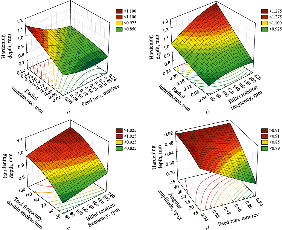
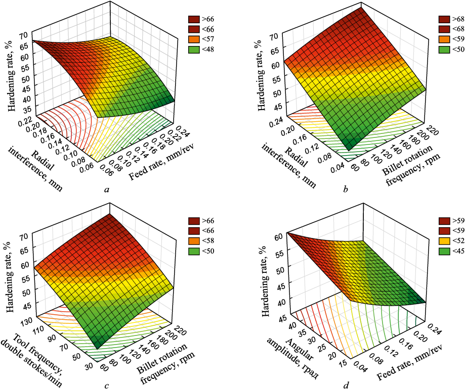
Figs. 6 and 7 illustrate the optimization results generated by Statistica 10.1.
Fig. 6. Depth response surfaces of the hardened layer of cylindrical surfaces
Fig. 7. Response surfaces of hardening degree of cylindrical surface |
Table 4 summarizes the statistical analysis and optimization undertaken for the depth of the hardened layer and the hardening rate. It was observed that certain sets of process variables yield the highest values for both the depth of the hardened layer (approximately 1.1 mm) and the hardening rate (about 65 %). This phenomenon arises from the clear relationship between the depth, hardening rate (HR), and each individual process variable. For instance, the parameters h and HR exhibit a direct proportionality with α, t, nb , ntool while displaying an inverse proportionality with the longitudinal feed s.
Table 4. Parameters and modes of pendulum SPD providing an increase
| |||||||||||||||||||||||||||||||
Results and Discussion
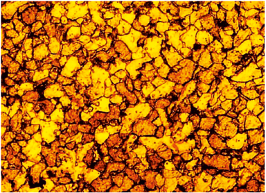
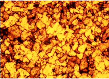
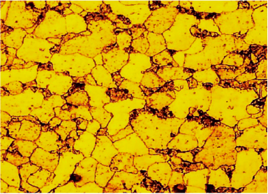
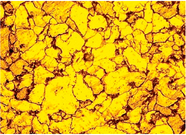
The phenomenon responsible for the strengthening of the metal is the impeding of dislocation motion. One method to hinder the motion of dislocations involves refining the grain structure. The accumulation of dislocations along grain boundaries obstructs the movement of dislocations, ultimately leading to the hardening of the metal [21 – 23]. Evaluating the effectiveness of the proposed mechanical hardening process can be achieved by assessing the improvements in the mechanical properties of the surface layer, primarily through changes in grain sizes and dislocation density (which is closely tied to the dimensions of the intergranular boundaries). Table 5 rovides an analysis of the microstructure properties observed on the surface of the sample and at its centerline. For components made from steel grade 45, the microstructure of the surface layer comprises dark spots indicating pearlite, and light spots representing ferrite.
Table 5. Microstructure of the hardened layer (steel 45) after pendulum SPD
| |||||||||||
The grain sizes within the core of the part that hasn’t been subjected to plastic deformation show minimal variation, remaining in the range of approximately 50 to 70 μm. Both the radial and axial cross-sections of the grains exhibit nearly identical features. Conversely, on the surface, the grain structure appears finer due to direct exposure to grinding and the effects of mechanical hardening. In this region, the microstructure primarily consists of grains compressed in the radial direction (the main deformation direction) and elongated along the axial direction (aligned with the direction of plastic flow). The concentration of pearlite grains is heightened, evident from the greater microhardness observed in the surface layer (as outlined in Table 5). The average widths of the grains measure 25 μm for ferrite and 30 μm for pearlite, while the average lengths are 35 μm for ferrite and 40 μm for pearlite.
It is evident that the treatment leads to a reduction in grain sizes within the hardened layers by approximately 30 to 40 %. Additionally, the notable increase in the concentration of fine, hard pearlite grains contributes to the heightened microhardness of the surface layer.
Theoretical investigations [21; 22] highlight that the hardening process of the surface layer can be comprehended through the lens of dislocation theory. According to this theory, metal hardening arises from the development of denser dislocation substructures and enhanced shear resistance within the lattice. Drankin B. et al. [22] substantiated that the creation of low-angle grain boundaries, coupled with an augmented dislocation density, curtails grain movement and reinforces the metal. This implies that a higher dislocation density corresponds to increased hardness of the metal. Sulima A. et al. [23] introduced the equation for dislocation density:
| \[\rho = {\left( {\frac{{0.27\left( {H{V_2} - H{V_1}} \right)}}{{amGb}}} \right)^2} + {\rho _0},\] | (4) |
where HV1 represents the initial surface microhardness; HV2 is the surface microhardness post plastic deformation; ρ0 = 108 cm\(^{-}\)2 is the initial dislocation density for carbon steels. Works [22; 23] present an inter-dislocation interaction parameter for ferritic steel as α = 0.32. G. Taylor estimated parameters for diverse polycrystal lattice types. They are: for BCC metal lattice m = 2,75; for steel grade 45 the shear modulus G = 78,000 MPa; the Burgers vector b = 3·10\(^{-}\)8 cm.
With the given values, we calculated the dislocation density 50 μm beneath the surface following pendulum tool treatment in the baseline mode, resulting in a value of 2.28·108 cm\(^{-}\)2.
This indicates that the pendulum tool treatment escalates dislocation density by a factor of 2.2 to 2.5. We compared these outcomes with values reported in [11; 12]. These studies indicate a 26 % increase in dislocation density after treatment with a standard roller and a 150 % increase after treatment with a two-radius roller.
In conclusion, it is imperative to note that the proposed pendulum tool process integrates both rolling and sliding, a unique characteristic not present in other existing hardening methods. Such a combination effectively reduces surface micro-roughness and enhancers the mechanical properties of the surface layer.
Conclusion
We have introduced a novel mechanical hardening process and developed the corresponding tooling. This process contributes to a notable increase in the hardness of the surface layer, achieving enhancements of approximately 9 to 12 % over the initial hardness.
Particularly significant is the microhardness elevation, ranging from 50 to 70 %. The resultant hardening depth lies within the range of 0.9 to 1.1 mm, and the corresponding hardening rate varies between 45 and 65 %.
By identifying optimal values for the process variables (nb = 160 ÷ 200 min\(^{-}\)1; ntool = 110 ÷ 130 double strokes/min; t = 0.15 ÷ 0.2 mm; s = 0.07 ÷ 0.11 mm/rev; α = 35 ÷ 40°), we have successfully determined the settings that yield the maximum depth of the hardened layer and hardening rate.
We have elucidated the rationale behind the improvement in surface layer properties, supported by both experimental findings and simulations. The research has revealed that, post-treatment, the average grain size experiences a reduction of 30 to 40 %, while the dislocation density undergoes a substantial increase of 150 %.
References
1. Laouar L., Hamadache H., Saad S., Bouchelaghem A., Mekhilef S. Mechanical surface treatment of steel – Optimization parameters of regime. Physics Procedia. 2009;2(3): 1213–1221. https://doi.org/10.1016/j.phpro.2009.11.084
2. Gorbunov A.V., Gorbunov V.F. Rationale for non-rigid shaft hardening depth under surface plastic deformation by centrifugal roller. Vestnik IrGTU. 2012;9(68):29–33. (In Russ.).
3. Zhang Z. Theoretical prediction of cross-sectional deformation of circular thin-walled tube in large elastic–plastic deformation stage under lateral compression. Thin-Walled Structures. 2022;180:109957. https://doi.org/10.1016/j.tws.2022.109957
4. Biswas S., Alavi S.H., Sedai B., Blum F.D., Harimkar S.P. Effect of ultrasonic vibration-assisted laser surface melting and texturing of Ti-6Al-4V ELI alloy on surface properties. Journal of Materials Science & Technology. 2019;35(2): 295–302. https://doi.org/10.1016/j.jmst.2018.09.057
5. Li Y.B., Zhang Q.X., Qi L., David S.A. Improving austenitic stainless steel resistance spot weld quality using external magnetic field. Science and Technology of Welding and Joining. 2018;23(7):619–627. https://doi.org/10.1080/13621718.2018.1443997
6. DiGiovanni C., Biro E., Zhou N.Y. Impact of liquid metal embrittlement cracks on resistance spot weld static strength. Science and Technology of Welding and Joining. 2019;24(3):218–224. https://doi.org/10.1080/13621718.2018.1518363
7. Grzesik W., Rech J., Żak K. High-precision finishing hard steel surfaces using cutting, abrasive and burnishing operations. Procedia Manufacturing. 2015;1:619–627. https://doi.org/10.1016/j.promfg.2015.09.048
8. Chen X.S., Li Q., Fei S.M. Constrained model predictive control in ball mill grinding process. Powder Technology. 2008;186(1):31–39. https://doi.org/10.1016/j.powtec.2007.10.026
9. Roux J.D.L., Craig I.K. Requirements for estimating the volume of rocks and balls in a grinding mill. IFAC-PapersOnLine. 2017;50(1):1169–1174. https://doi.org/10.1016/j.ifacol.2017.08.403
10. Mitrofanova K.S. Investigating the quality of steel 45 surface layer after surface plastic deformation with a milt-radius roller. In: Proceedings of the Conf. “Innovations in Mechanical Engineering”. 2019:639–787. (In Russ.).
11. Zaides S.A. Handbook on Surface Plastic Deformation Processes. Irkutsk: IRNITU; 2021:504. (In Russ.).
12. Сuong N.K. Improving the quality of low-rigid shafts by surface plastic deformation in cramped conditions: Cand. Tech. Sci. Diss. Irkutsk; 2018:149. (In Russ.).
13. Yaman N., Sunay N., Kaya M., Kaynak Y. Enhancing surface integrity of additively manufactured Inconel 718 by roller burnishing process. Procedia CIRP. 2022;108:681–686. https://doi.org/10.1016/j.procir.2022.03.106
14. Frihat M.H., Al Quran F.M.F., Al-Odat M.Q. Experimental investigation of the influence of burnishing parameters on surface roughness and hardness of brass alloy. Material Science & Engineering. 2015;5(1):1–4. https://doi.org/10.4172/2169-0022.1000216
15. Ezhelev A.V., Bobrovskii I.N., Luk’yanov A.A. Analysis of processing ways by superficial and plastic deformation. Fundamental’nye issledovaniya. 2012;(6–3):642–646. (In Russ.).
16. Kotenok V.I., Podobedov S.I. Energy-efficient design of rolls for ball-rolling mills. Metallurgist. 2001;45(9–10):363–367.
17. Tomczak J., Pater Z., Bulzak T. The flat wedge rolling mill for forming balls from heads of scrap railway rails. Archives of Metallurgy and Materials. 2018;63(1):5–12. https://doi.org/10.24425/118901
18. Chumachenko E.N., Aksenov S.A., Logashina I.V. Mathematical modeling and energy conservation for rolling in passes. Metallurgist. 2010;(8):498–503.
19. Zaides S.A., Ho Minh Quan. Method for surface-plastic deformation of outer surface of a part in the form of body of revolution. Patеn RF no. 2757643. Publ. 19.10.2021. (In Russ.).
20. Zaides S.A., Kho Min’ Kuan. Pendulum surface plastic deformation of cylindrical blanks. Izvestiya. Ferrous Metallurgy. 2022;65(5):344-353. (In Russ.). https://doi.org/10.17073/0368-0797-2022-5-344-353
21. Prikhod’ko V.M., Petrova L.G., Chudina O.V. Metallophysical Foundations for Hardening Technologies Development. Moscow: Mashinostroenie; 2003:384. (In Russ.).
22. Drapkin B.M., Kononenko V.K., Bez”yazychnyi V.F. Properties of Alloys in Extreme State. Moscow: Mashinostroenie; 2004:256. (In Russ.).
23. Sulima A.M., Shulov V.A., Yagodkin Yu.D. Surface Layer and Operational Properties of Machine Parts. Moscow: Mashinostroenie; 1988:146-149. (In Russ.).
About the Authors
S. A. ZaidesRussian Federation
Semen A. Zaides, Dr. Sci. (Eng.), Prof. of the Chair of Materials Science, Welding and Additive Technologies
83 Lermontova Str., Irkutsk 664074, Russian Federation
Ho Minh Quan
Russian Federation
Ho Minh Quan, Postgraduate of the Chair of Materials Science, Welding and Additive Technologies
83 Lermontova Str., Irkutsk 664074, Russian Federation
Review
For citations:
Zaides S.A., Quan H.M. Degree and depth of hardening under pendulum surface plastic deformation of carbon steel. Izvestiya. Ferrous Metallurgy. 2023;66(3):272-282. https://doi.org/10.17073/0368-0797-2023-3-272-282


