Scroll to:
Development of shear deformation in lath martensite of medium alloy steels under tension
https://doi.org/10.17073/0368-0797-2023-2-154-161
Abstract
Evolution of shear deformation in steel with the structure of tempered martensite was studied under active tension. Purpose of the work was to identify the patterns of deformation development at the scale-structural levels: lath, plate, fragment of a package and a lath. The authors investigated the deformation relief formed at different stages of plastic deformation by optical, transmission and scanning electron microscopy. Quantitative characteristics of the deformation relief were measured: shear strength (P), distance (X) between the shear traces and their length. Statistical processing was carried out, the average values and relationship with the degree of plastic deformation were determined. It was established that development of shear deformation in the lath component of martensite occurs with the formation of two subsystems of shear traces: thin and coarse. Subsystems of thin traces are formed from the very beginning of plastic deformation. Appearance and evolution of the subsystem of coarse traces correlates with formation of the first (long) neck in the sample, and it is the main mechanism leading to the localization of plastic deformation on the sample scale. The places of localization of rough shift are the border areas of the laths and fragments of the package. Connection between localization of subsystems of coarse shear traces and formation of a fragmented dislocation structure were revealed. The values of the average shear power in thin <Pf> and coarse <Ps> traces do not depend on the degree of local plastic deformation of the sample in the entire range of deformation degrees and remain constant until destruction (<Pf> = 0.1 μm and <Ps> = 0.3 μm).
For citations:
Teplyakova L.A., Kashin A.D., Kunitsyna T.S. Development of shear deformation in lath martensite of medium alloy steels under tension. Izvestiya. Ferrous Metallurgy. 2023;66(2):154-161. https://doi.org/10.17073/0368-0797-2023-2-154-161
Introduction
Structural steels with a quenched and tempered martensite structure exhibit excellent plastic properties and high strength, both during the onset of plastic deformation [1 – 3], and at significant degrees of deformation [4 – 6]. The internal structure of such steels is hierarchically organized at a range of scales, from millimeters to tens of nanometers [7; 8]. Upon tensile deformation of tempered martensite steels, macro-localization of plastic deformation occurs, resulting in the formation of one or two necks, a (long and short neck [9]. Both necks form in accordance with the Considère criterion σ = θ (where σ is the stress existing in the sample and θ is the coefficient of deformation hardening). Notably, there is a unique interrelation between the value of the area of macro-localization of deformation and steel plasticity, with more plastic steel resulting in a higher bulk of the sample involved in the macro-localization of deformation. Later studies revealed experimental regularities in the localization of plastic deformation in a grain ensemble composed of inherited austenite and actual grains of martensitic steel [7]. These studies established that plastic deformation self-organizes in groups of actual grains during active loading, with the linear sizes of the martensite grains self-organizing during deformation comparable to those of the inherited austenitic grains. In other words, plastic deformation during loading is closely related to the grain subsystem.
This work aims to detect the regularities of plastic deformation localization at the scale of martensitic constituents, including lath, plate, lath fragment, and rack.
Experimental
For this study, 0.34С1Cr3Ni1Mo1VFe steel was selected. After undergoing rolling during the final stage of thermal treatment, the steel was quenched in water from a temperature of 950 °C, followed by tempering at 600 °C for 4 h with subsequent water cooling. The resulting structure of the steel is high-temper mixed lath-plate martensite. It should be noted that all carbon is contained within carbide deposits, including cementite and special carbides, mainly Me2C, Me6C and Me23C. The average linear sizes of martensite structural constituents are provided:
|
The structure of the steel comprises three main components: the boundaries of all martensite structural elements; a developed dislocation structure with a dislocation density of approximately 1010 cm\(^{-}\)2; and a subsystem of carbide phases consisting of cementite and special carbides. The dislocation structure exhibits diversity and is classified into the following types: mesh, cellular and fragmented [10]. Cementite deposits are primarily localized at the boundaries of martensite structural constituents, while the location of special carbides is closely associated with the dislocation substructure. In the mesh-type substructure, special carbides are situated at the mesh nodes, while in the cellular and fragmented substructures, they are located at the junctions of cell and fragment boundaries, respectively [7].
To study the deformation relief formed on the preliminary polished surface of samples during plastic deformation, the steel was deformed by tension using an Instron machine at a rate of 6·10\(^{-}\)4 s\(^{-}\)1 at ambient temperature. Various analytical methods were employed, including optical, transmittance (on replicas), and scanning electron microscopy. Quantitative properties of the deformation relief, such as shear power (P) in slip traces, distance between traces (X), and trace length (L) were measured. The results of the measurement were statistically processed to obtain their average values.
Results and discussion
Shear trace. Systems of shear traces
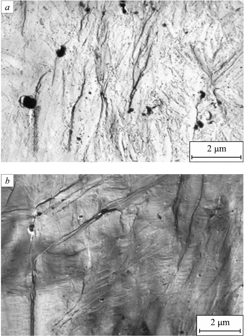
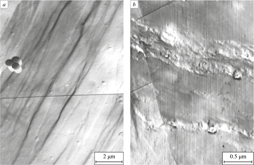
The shear traces present in the studied steel are primarily located at the boundaries of individual laths and plates, as evidenced by the surface images pre-etched on martensite (Fig. 1, a). Typically, these shear traces are found at angles close to 45° with respect to the loading axis. In laths, the first shear traces are generally oriented parallel to the lath habitus plane, resulting in shear occurring in parallel to the rack long boundaries along {011} planes. Meanwhile, in plates, the shear traces are mainly oriented at an angle to the habitus plane. As the degree of deformation increases, the density of shear traces in laths and plates increases, leading to the formation of primary shear systems. Subsequently, secondary shear systems occur, oriented at higher angles to the primary traces. Fig. 1, b illustrates a local surface segment of a deformed sample (εloc = 0.1), where multiple systems of primary shear traces are visible. The primary shear traces are curvilinear for most of their length, a characteristic commonly observed in metals and alloys with a BCC lattice [11; 12] and specifically, in α-iron [13; 14].
Fig. 1. Micrographs of the sample surface of 0.34С1Cr3Ni1Mo1VFe steel |
In summary, the pattern of shear traces that formed during the plastic deformation of martensite laths exhibits distinct features, including discrete average shear power, attachment to misorientation boundaries, discontinuity; blur, and the existence of a fine structure of shear trace.
Shear power
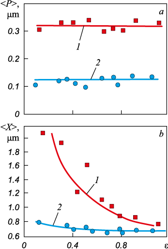
As previously mentioned, the initial shear traces in laths occur along the long side of the rack at the lath boundaries. As the degree of deformation increases, shear traces also appear within the laths, initially oriented parallel to the long side of the rack and at higher deformation degrees at an angle to the rack boundaries (secondary shears). The shear traces exhibit a pattern of both low and high shear power, which can be referred to as fine and coarse traces, respectively. In this study, the average shear power (<P>) was measured for both the primary and secondary shear subsystems. The dependence of <P> on the degree of deformation is presented in Fig. 2, a, showing that the average shear power for both subsystems remains almost constant as the degree of deformation increases, with values of approximately 0.1 μm for fine traces and 0.3 μm for coarse traces.
Fig. 2. Dependence of the average shear power in coarse (1) and thin (2) shear traces (a) |
Density of shear traces. Attachment to boundaries
The density of shear traces in the primary systems increases with the degree of deformation at its initial stages. This is evident from the dependence of the measured distance between the traces (X) on the degree of local deformation ε, as shown in Fig. 2, b. The measurements were made separately for fine and coarse traces, and the respective dependence of average <X> on the deformation degree is illustrated in the same figure. Analysis of the obtained dependences and comparison of <X> with the transversal sizes of a rack provide the following observations. At the beginning of deformation, the average distance between coarse shear traces <Xs > is comparable to the width of the lath. Before destruction, there is one coarse trace in average for every 4 – 5 racks, and the average distance between them becomes equal to the average width of a lath fragment. The density of fine traces is several times higher than that of coarse ones, and their occurrence follows a regularity such that before destruction, one fine trace occurs per rack on average. Comparison of the average distance between the traces <X> with the average transversal size of laths, plates and racks demonstrated that the systems of fine shear traces are mainly formed inside the racks and plates along their habitus plane. On the other hand, the occurrence of coarse traces is related to shear in the near boundary regions of the martensite structural constituents such as such as racks, lath fragments, laths, and plates [15 – 17].
Length of shear traces. Discontinuity of traces
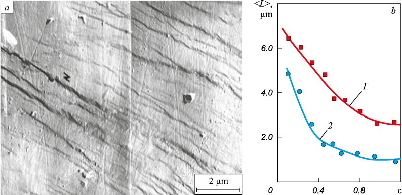
The primary system traces exhibit discontinuity, as depicted in Fig. 3, a. Although appearing continuous at low magnification and having an average length similar to that of a rack, they are, in fact, composed of brief segments of traces that are much shorter than the rack’s length. This study measured the length of shear traces (L), determined its average value, and established its correlation with the degree of local deformation. Fig. 3, b shows the resulting L(ε) curve.
Fig. 3. Intermittent shear traces on the surface of the 0.34С1Cr3Ni1Mo1VFe steel sample |
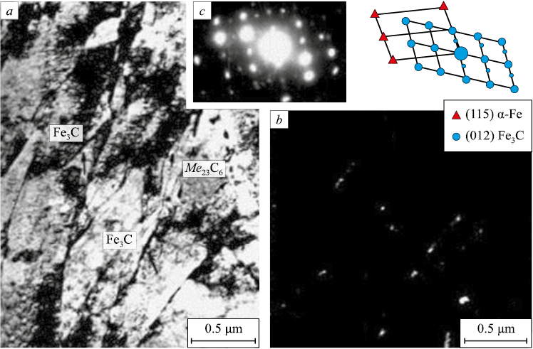
Figures 4, a, b display typical image of fine structure of the examined steel, obtained through transmittance electron microscopy in light and dark fields. Comparing the average trace length (<L>) with the average sizes of the lath and/or rack along the habitus plane, it is evident that, at the onset of plastic deformation, the trace length is similar to that of the lath size. Subsequently, the average trace length decreases to <L> = 1.2 μm during further deformation and remains constant until failure. This value corresponds to the average distance between cementite deposits at the rack boundaries for the steel under consideration.
Fig. 4. Thin-plate cementite precipitation at the laths borders: |
Fig. 4, a and b depict the location of carbide phases in the laths of the steel, including the positioning of cementite deposits at the rack boundaries. By comparing the morphology of the shear traces and the average distance between them with the distribution pattern of cementite deposits a correlation between the pattern of shear traces and cementite distribution within the lath was identified. In 0.34С1Cr3Ni1Mo1VFe steel after high temper, the presence of fine cementite deposits mainly at the boundaries of a rack is the primary cause of shear localization in the near-boundary region of a rack, where systems of coarse shear traces are observed. Consequently, significant shear localization in the near-boundary region of racks leads to the destruction of cementite deposits and carbon yield into solid solution and on lattice defects [18; 19].
Blurring of shear traces
It is widely understood [20] that in FCC metals and alloys, where the shear planes are strictly defined (i.e., planes of dense packing), the observed shear traces on the surface of a deformed sample are formed as a result of the emergence of dislocations slipping in one or more close, parallel planes, referred to as slip traces. The shear strength within these traces (P) is determined by the number of dislocations that have occurred and is numerically equivalent to the shift of crystal parts along these planes [21]. In FCC crystals, at least upon moderate deformation, the slip traces are limited by nearly parallel straight lines, and with known crystallographic conditions, the shear strength can be determined accurately enough. Such data are currently available, for instance, in [15; 21]. However, in crystals with a BCC lattice, which are characterized by a rather complicated volumetric splitting of total dislocations [12], the slip planes are not as strictly defined. As a result, dislocation can easily change the slip plane (pencil glide), causing the slip traces to become blurred. Figure 5, a illustrates the pattern of shear traces observed in the considered steel, where a significant portion of the traces has indistinct boundaries. In this steel, the blurring effect is not only due to the type of martensite crystal lattice (BCC), but also the relatively high density of dislocations in the racks, particularly near their boundaries.
Fig. 5. Blurred shear traces (a) and thin structure of shear traces (b) at ε = 0.1 |
Fine structure of shear traces
Targeted studies of the deformation relief using magnifications in the range of 200 – 40,000 have revealed the fine structure of shear traces. Shear traces, which appear to be continuous at low magnifications, often have a complex internal structure (Fig. 5, b).
Comparing the structure of shear traces with respective elements of substructure [7; 18], analyzed by TEM, has demonstrated that the fine structure of such traces can be related to the formation of fragmented substructure in certain racks and their groups during plastic deformation. This formation of the fragmented substructure in the racks is also confirmed by scanning electron microscopy. It should be noted that shear traces with fragmentation are characteristic of deformation degrees close to destruction.
Average shear value
By utilizing the average shear power in the traces and the average distance between the traces, it is feasible to estimate the average shear (γ) localized in them: <γ> = <P>/<X>. At the stage of homogeneous macrolevel deformation of the considered steel (ε ≤ 0.1), the relative shear in fine traces <γ f > was found to be 0.16, whereas in coarse shear traces <γs > was 0.10.
At the stage of macro localization of deformation, <γ f > increased to 0.65 and <γs > to 0.5, and these values were retained until the sample’s failure. Thus, the relative shear values obtained in this research, which were localized at the scale of the lath and/or lath fragment, are ultimate for 0.34С1Cr3Ni1Mo1VFe steel.
Conclusions
The present study investigates the evolution of deformation relief of the 0.34С1Cr3Ni1Mo1VFe steel with tempered martensite structure under plastic deformation.
The study quantitatively examines the development of shear deformation in the martensite lath constituent, resulting in the formation of two subsystems of shear traces: fine and coarse. The fine subsystem is formed from the beginning of plastic deformation under uniform deformation conditions, while the coarse subsystem appears with the formation of the first neck in the sample and is responsible for macro localization of plastic deformation.
The study determined that coarse shear tends to occur in the boundary regions of racks and lath fragments. This finding suggests a correlation between the formation of subsystems of coarse shear traces and the fragmented dislocation structure observed in the lath.
Based on a high-statistics analysis of deformation relief, the study experimentally established that the average shear power in fine <Pf > and coarse <Ps > traces does not vary with the degree of local plastic deformation observed in the steel during tension, across the entire range of deformation degrees studied. These values remained constant up to the point of destruction and were found to be <Pf > = 0.1 μm and <Ps > = 0.3 μm.
The study also uncovered quantitative relationships between the average shear power in the subsystems of fine <Pf > and coarse <Ps > shear traces and the average transverse sizes of martensite crystals in the considered steel. Specifically, <Pf > was found to be approximately half the rack width, while <Ps > was equal to double rack width.
Additionally, the study found that in the high temper martensite structure of the steel, there exists an ultimate value of average relative shear localized in the scales of the lath and/or lath fragment, which equals 0.5.
References
1. Ivanov Yu.F., Gromov V.E., Popova N.A., Konovalov S.V., Koneva N.A. Structural-Phase States and Mechanisms of Hardening of Deformed Steel. Novokuznetsk: Poligrafist; 2016:510. (In Russ.).
2. Harjo S., Kawasaki T., Tomota Y., Gong W., Aizawa K., Tichy G., Shi Z., Ungár T. Work hardening, dislocation structure, and load partitioning in lath martensite determined by in situ neutron diffraction line profile analysis. Metallurgical and Materials Transactions A. 2017;48(9):4080–4092. https://doi.org/10.1007/s11661-017-4172-0
3. Kwak K., Mayama T., Mine Y., Takashima K. Anisotropy of strength and plasticity in lath martensite steel. Materials Science and Engineering: A. 2016;674:104–116. https://doi.org/10.1016/j.msea.2016.07.047
4. Jo K.-R., Seo E.-J., Sulistiyo D.H., Kim J.-K., Kim S.-W., De Cooman B.C. On the plasticity mechanisms of lath martensitic steel. Materials Science and Engineering: A. 2017;704: 252–261. https://doi.org/10.1016/j.msea.2017.08.024
5. Jafarian H.R., Tarazkouhi M.F. Significant enhancement of tensile properties through combination of severe plastic deformation and reverse transformation in an ultrafine/nano grain lath martensitic steel. Materials Science and Engineering: A. 2017;686:113–120. https://doi.org/10.1016/j.msea.2017.01.034
6. Shamsujjoha M. Evolution of microstructures, dislocation density and arrangement during deformation of low carbon lath martensitic steels. Materials Science and Engineering: A. 2020;776:139039. https://doi.org/10.1016/j.msea.2020.139039
7. Teplyakova L., Gershteyn G., Popova N., Kozlov E., Ignatenko L., Springer R., Schaper M., Bach Fr.-W. Scale‐dependent hierarchy of structural elements in the microstructure of thermomechanical treated ferritic steels with residual austenite. Materialwissenschaft und Werkstofftechnik. 2009; 40(9):704–712. https://doi.org/10.1002/mawe.200900503
8. Morsdorf L., Jeannin O., Barbier D., Mitsuhara M., Raabe D., Tasan C.C. Multiple mechanisms of lath martensite plasticity. Acta Materialia. 2016;121:202–214. https://doi.org/10.1016/j.actamat.2016.09.006
9. Teplyakova L.A., Popova N.A., Kozlov E.V. Localization of plastic deformation in tempered martensitic steels at large-scale levels. Fundamental problems of modern materials science. 2012;9(4-2):659–663. (In Russ.).
10. Glezer А.M., Kozlov E.V., Koneva N.A., Popova N.A., Kurzina I.A. Plastic Deformation of Nanostructured Materials. CRC Press; 2017:334.
11. Redikul’tsev A.A., Uritskii A.G., Puzanov M.P., Belyaevskikh A.S. Formation of internal structure in the deformation zone during rolling of the BCC single crystal (110)[001]. Izvestiya. Ferrous Metallurgy. 2017;60(3):207–215. (In Russ.). https://doi.org/10.17073/0368-0797-2017-3-207-215
12. Sadanov E.V. Crystal geometry of screw dislocation glide in tungsten nanocrystals. Physics of the Solid State. 2015;57(2): 249–254. https://doi.org/10.1134/S1063783415020298
13. Novák V., Šesták B., Zárubová N. Plasticity of high purity iron single crystals (II) surface observations. Crystal Research and Technology. 1984;19(6):793–807. https://doi.org/10.1002/crat.2170190611
14. Xie K.Y., Wang Y., Ni S., Liao X., Cairney J.M., Ringer S.P. Insight into the deformation mechanisms of α-Fe at the nanoscale. Scripta Materialia. 2011;65(12):1037–1040. https://doi.org/10.1016/j.scriptamat.2011.08.023
15. Kozlov E.V., Popova N.A., Ignatenko L.N., Grigor’eva N.A., Kovalevskaya T.A., Teplyakova L.A., Chukhin B.D. Stages of plastic deformation, structure evolution and sliding pattern in alloys with dispersed hardening. Izvestiya vuzov. Fizika. 1991;(3):112–128. (In Russ.).
16. Mine Y., Hirashita K., Takashima H., Matsuda M., Takashima K. Micro-tension behaviour of lath martensite structures of carbon steel. Materials Science and Engineering: A. 2013;560:535–544. https://doi.org/10.1016/j.msea.2012.09.099
17. Du C., Hoefnagels J.P.M., Vaes R., Geers M.G.D. Plasticity of lath martensite by sliding of substructure boundaries. Scripta Materialia. 2016;120:37–40. https://doi.org/10.1016/j.scriptamat.2016.04.006
18. Kozlov E.V., Teplyakova L.A., Popova N.A., Ignatenko L.N., Klopotov A.A., Koneva N.A. Influence of substructure type on carbon redistribution in martensitic steel during plastic deformation. Izvestiya vuzov. Fizika. 2002;45(3):72–86. (In Russ.).
19. Koneva N.A., Popova N.A., Nikonenko E.L. Internal stresses and their sources in BCC and FCC steels. Solid State Phenomena. 2020;303:128–142. https://doi.org/10.4028/www.scientific.net/SSP.303.128
20. Neuhäuser H. Slip-line formation and collective dislocation motion. In: Dislocations in Solids. 1983;6:319–440.
21. Lapsker I.A., Sharkeev Yu.P., Koneva N.A., Kozlov E.V. Electron microscopic method for determining the characteristics of sliding in grains of polycrystals with a fcc-lattice. Zavodskaya laboratoriya. Diagnostika materialov. 1998;(3): 32–35. (In Russ.).
About the Authors
L. A. TeplyakovaRussian Federation
Lyudmila A. Teplyakova, Dr. Sci. (Phys.–Math.), Prof. of the Chair of Physics
2 Solyanaya Sqr., Tomsk 634003, Russian Federation
A. D. Kashin
Russian Federation
Aleksandr D. Kashin, Postgraduate
2/4 Akademicheskii Ave., Tomsk 634055, Russian Federation
T. S. Kunitsyna
Russian Federation
Tat’yana S. Kunitsyna, Cand. Sci. (Phys.-Math.), Assist. Prof. of the Chair of Advanced Mathematics
2 Solyanaya Sqr., Tomsk 634003, Russian Federation
Review
For citations:
Teplyakova L.A., Kashin A.D., Kunitsyna T.S. Development of shear deformation in lath martensite of medium alloy steels under tension. Izvestiya. Ferrous Metallurgy. 2023;66(2):154-161. https://doi.org/10.17073/0368-0797-2023-2-154-161
JATS XML


